5-4 srellortnoC evirD 30EVIRDOCE610-3.**CKD 30EVIRDOCE
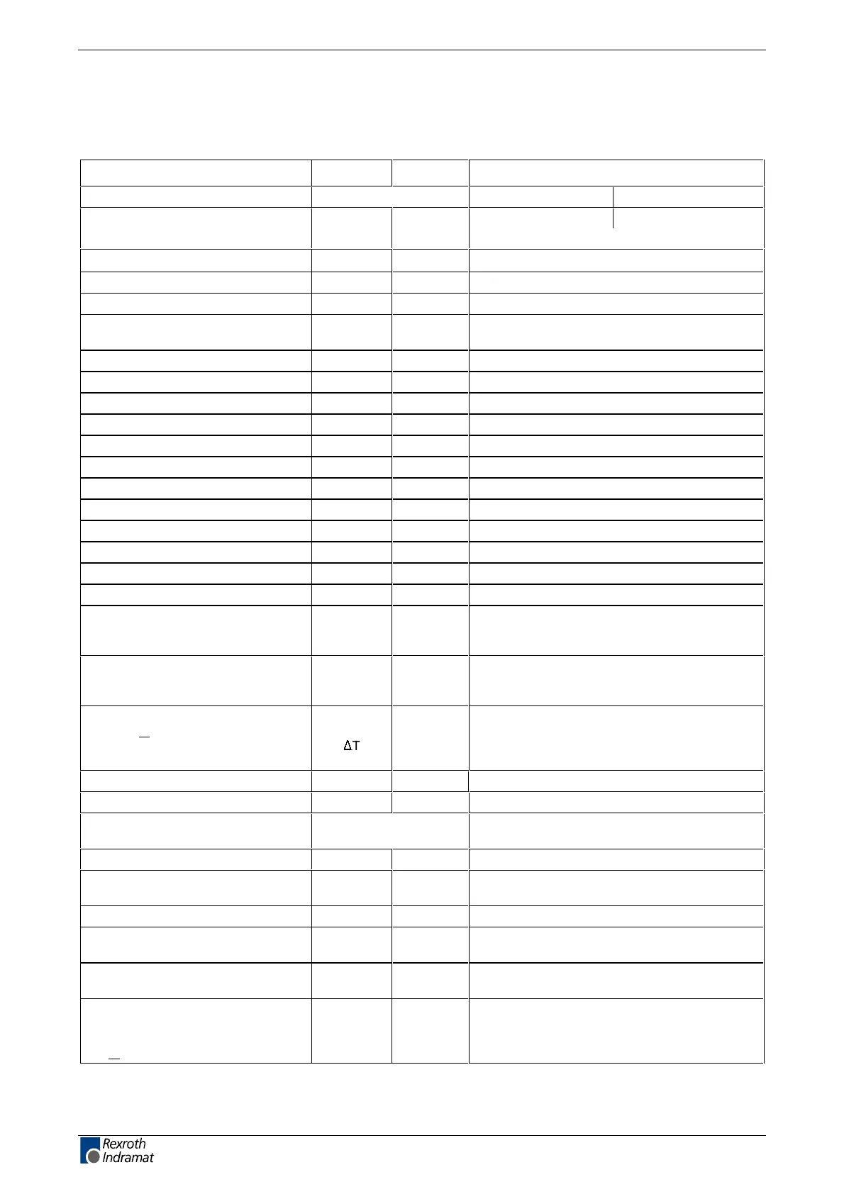
Electric Data of the Individual DKC**.3-016 Components
Mains connections, Power section DKC**.3-016-FW
tinUlobmySnoitangiseD
DKC**.3-016-7-FW
esahp eerhtesahp elgnissniam eht ta edom gnitarepO
Uegatlov tupni sniaM
N1
V 1 x AC 3 x AC
(200 ... 480) ± 10%
fycneuqerf sniaM
N1
Hz
(50 ... 60
) ± 2
esiwkcolc-retnuoc ro esiwkcolcdleif yratoR
Sdaol detcennoC
N1
kVA see page 11-1: "Mains Connections"
Nominal charging current
(dependent on mains input voltage)
1.2 ... 2.8
Rrotsiser trats-tfoS
Softstart
Ohm
240
Continuous power soft-start resistor P
Softstart
kW
0.05
2)
Switching frequency (selectable) f
S
kHz
4 or 8
Type current = peak current 1 I
PEAK1
A
16
1)
Peak current 2 for f
S
= 4 kHz I
PEAK2(4kHz)
A
6
1)
Peak current 2 for f
S
= 8 kHz I
PEAK2(8kHz)
A
5
1)
Continuous current 1 for f
S
= 4 kHz I
CONT1(4kHz)
A
4
1)
Continuous current 2 for f
S
= 4 kHz I
CONT2(4kHz)
A
6
1)
Continuous current 1 for f
S
= 8 kHz I
CONT1(8kHz)
A
2.8
1)
Continuous current 2 for f
S
= 8 kHz I
CONT2(8kHz)
A
5
1)
Max. output frequency at f
S
=4 kHz f
out
Hz
400
Max. output frequency at f
S
=8 kHz f
out
Hz
800
Device power dissipation without
internal continuous bleeder power
for I
CONT2
P
V
08W
(see page 12-1: "Power dissipation")
Peak bleeder power DKC
when U
ZW
= 850 V
for permissible load cycle
P
BS
7.2Wk
0.29 s on, 20 s o
Continuous bleeder power DKC
when T
a
< 45 °C
under max. temperature range
with distance
P
BD
d
kW
K
mm
0.05
40 K
80 (see page 12-7)
Max. energy dissipation W
R,MAX
0.1sWk
Wegrahc sub CD .xaM
MAX
0.1sWk
Internal DC bus dynamic brake
(ZKS)
not present
RSKZ rof rotsiseR
ZKS
tneserp tonmhO
Storable energy of the DC bus
capacitors
W
ZW
Ws see diagrams page 5-9: "Storable energy in the
bus"
Nominal DC bus capacitance DKC C
ZW
%02± 531.0Fm
DC bus voltage
(dependent on mains input voltage)
U
ZW
008 ... 003 CDV
DC bus continuous power
(dependent on mains input voltage)
P
ZWD
see diagrams page 5-12 "Allowed DC bus
continuous power"
max. DC bus continuous power
for a single source supply where
U
N1
= 3 x AC 400 V, when
Ta < 45 °C
P
ZWD
5.0Wk
customerservice@hyperdynesystems.com | (479) 422-0390

 Loading...
