4-40 ECODRIVE03 DKC**.040, DKC**.100, DKC**.200 ECODRIVE03 Drive Controllers
4.2 Electrical connections - independent of the drive
controller type
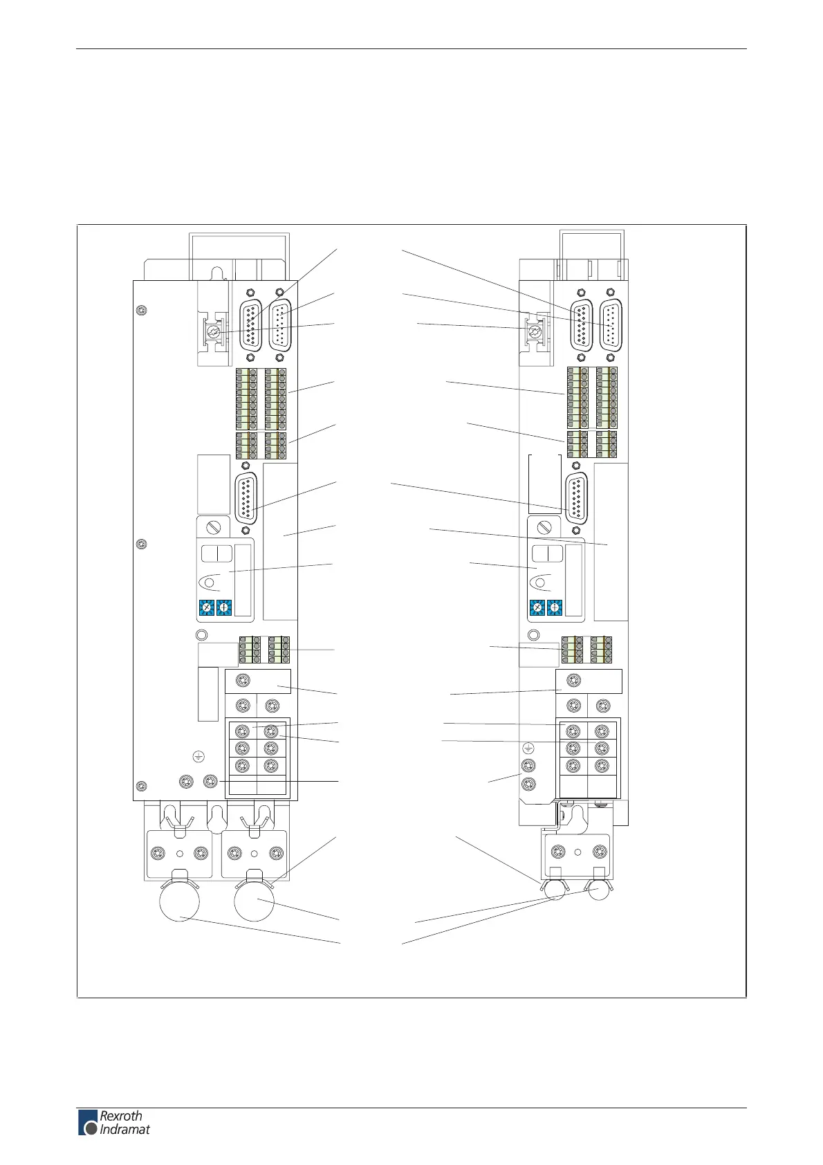
A look at the drive controller and connector designations
Front view
X3:
digital and analog
in-/ outputs
X1:
control voltage supply
and control signals
X2:
RS232/
RS485
X6:
motor temperature monitoring
holding brake
X5:
DC bus connection
mains connection
motor connection
X4:
encoder 1
X8:
encoder 2
DKC**.3-100-7-FW
DKC**.3-040-7-FW
FA5026f1.fh7
motor cable
line input
Barcode
0
1
2
3
4
5
6
7
8
9
0
1
2
3
4
5
6
7
8
9
H1
S1
S3 S2
Barcode
0
1
2
3
4
5
6
7
8
9
0
1
2
3
4
5
6
7
8
9
H1
S1
S3 S2
Barcode
Typenschild
Barcode
Typenschild
123 4 5 6 7 8 9 1 2 3 4
10 1112 131415161718
5 6 7 8
123 4 5 6 7 8 9 1 2 3 4
11121314 15161718
5 6 7 8
123 4
567 8
123 4
567 8
XE2
XE1
XE1XE2
XS1:
cable clamp
shield connections
- complete shield motor cable
- holding brake
- motor temp. monitoring
L+
L-
L1
L2
L3
A1
A2
A3
L+
L-
L1
L2
L3
A1
A2
A3
XS2:
cable clamp
shield connections
device-typical
interface
X7:
programming module
(rmware, parameter)
H1 - diagnosis indicator
S1 - fault clearance button
S2, S3 - adress switch
XE1: protective conductor
connection (motor)
XE2: protective conductor
connection (mains)
Fig. 4-43: Front view DKC**.3-040-7-FW and DKC**.3-100-7-FW with
Connectors
customerservice@hyperdynesystems.com | (479) 422-0390

 Loading...