4-62 ECODRIVE03 DKC**.040, DKC**.100, DKC**.200 ECODRIVE03 Drive Controllers
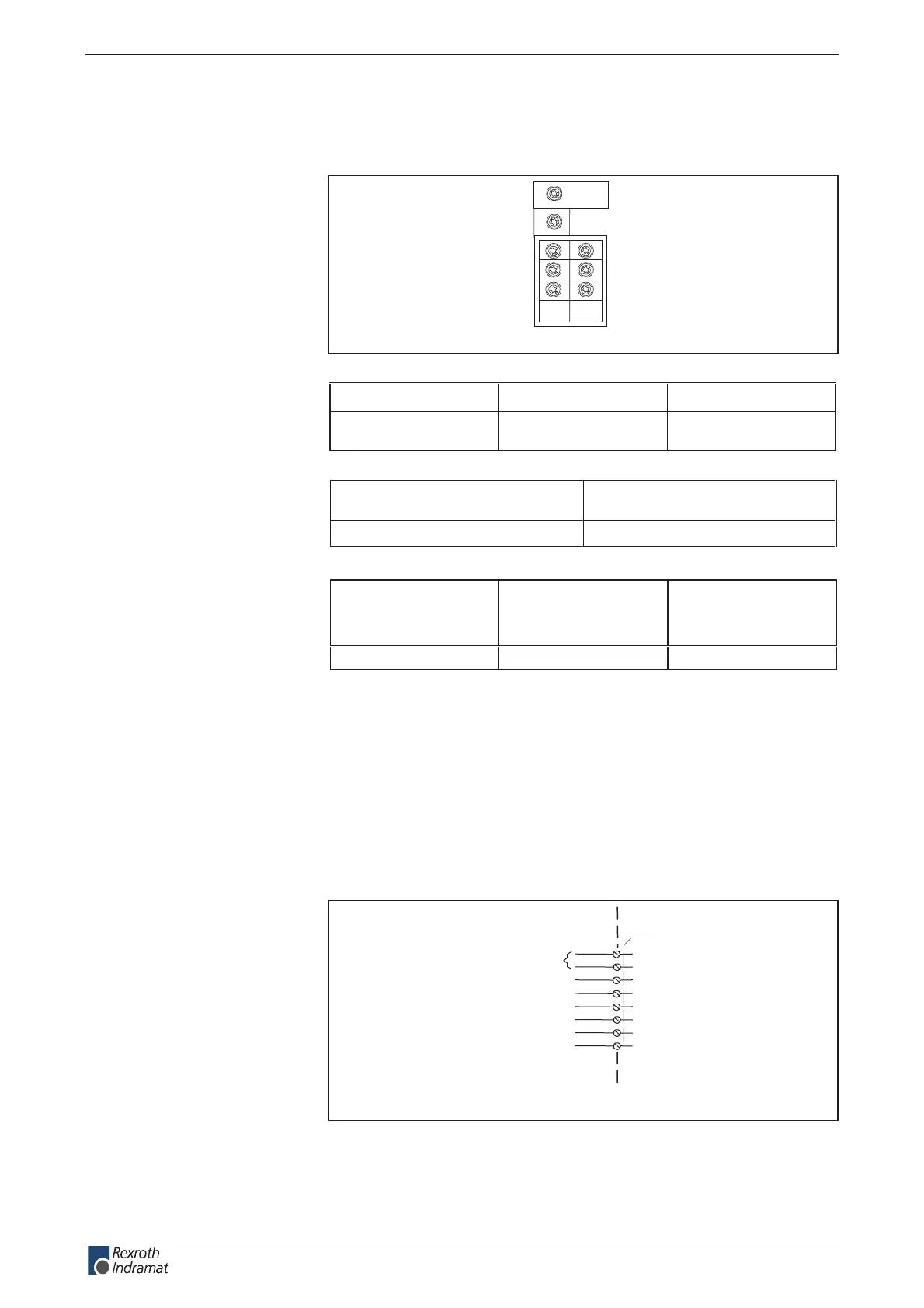
X5, DC bus, Motor and Mains Connections
Technical description of connector
Ap5267f1.FH7
L+
L-
L1
L2
L3
A1
A2
A3
Fig. 4-89: Connector X5
Type No. of pins Design
connection block 2 / 3 / 3 screw-in connection for
ring terminals M5
Fig. 4-90: Design
min. tightening torque
[Nm]
max. tightening torque
[Nm]
0.35.2
Fig. 4-91: Tightening torque
Cross section
single wire
[mm ²]
max. connectable
cross section
[mm ²]
max. Cross section
in AWG
gauge no.:
--52--
Fig. 4-92: Connection cross section
DC bus connection
The DC bus connection connects several controllers to each other plus it
connects controllers together with auxiliary components
• Increase allowed DC bus continuous power
• Increase allowed bleeder continuous load
• Allow connections for "Central supply"
device-external device-internal
AP5301F1.FH7
X5
L+
L-
DC bus connection
Fig. 4-93: DC bus connection
Illustration:
Design:
Tightening torque:
Connection cross section:
Connection
DC bus:
customerservice@hyperdynesystems.com | (479) 422-0390

 Loading...