ECODRIVE03 Drive Controllers ECODRIVE03 DKC**.040, DKC**.100, DKC**.200 4-61
Signal allocation to the actual position value
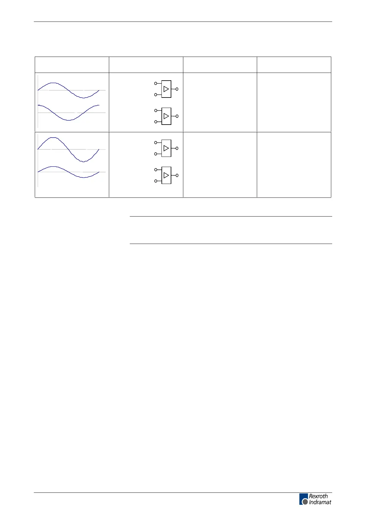
Signal allocation (X4) signal designation signal form actual position value
(with default setting)
G1Sin+(S3)
G1Sin- (S1)
G1Cos+(S4)
G1Cos- (S2)
DSF
(sine 1 Vss without
120 Ohm matching resistor,
I²C-Bus)
increasing
amplitude-modulated signal
G1Sin+(S3)
G1Sin- (S1)
G1Cos+(S4)
G1Cos- (S2)
Resolver increasing
Fig. 4-88: Signal allocation to the actual position value
Note: default setting:
=> see rmware functional description: "Motor Encoder"
(Encoder 1).
Connecting the Measuring System
See page 1-4: "An Overview of Measuring Systems Supported".
customerservice@hyperdynesystems.com | (479) 422-0390

 Loading...