ECODRIVE03 Drive Controllers ECODRIVE03 DKC**.040, DKC**.100, DKC**.200 4-45
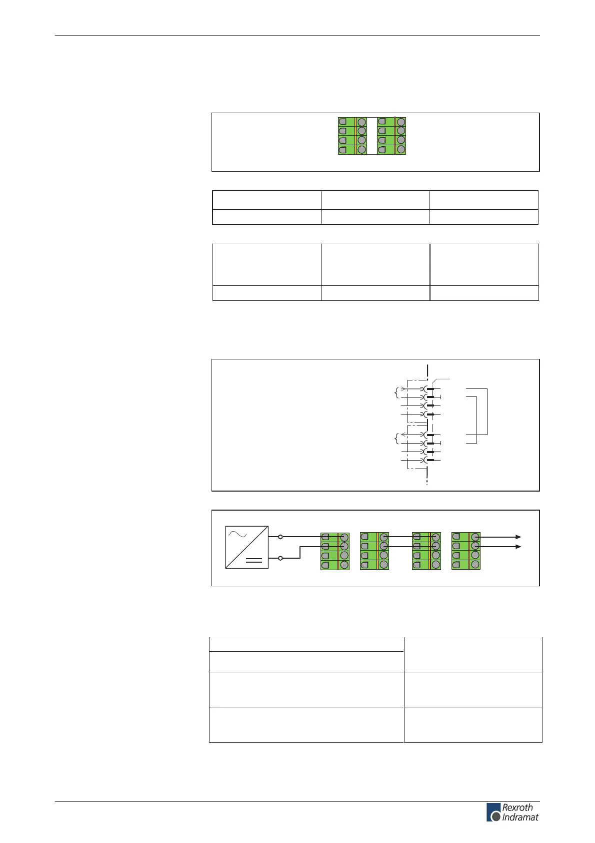
X1, Connections for Control voltage
Technical description of connector
Ap5264f1.FH7
123 4
567 8
Fig. 4-48: Connector X1
Type No. of pins Design
Spring contact 2 x 4 Bushing on connector
Fig. 4-49: Design
Cross section
single wire
[mm ²]
Cross section
multi core wire
[mm ²]
Cross section
in AWG
Gauge no.:
0,2-2,5 1,5-2,5 16-12
Fig. 4-50: Connection cross section
24V control voltage supply (+24V and 0V)
AP5121F1.FH7
+24V
+24V
0V
0V
X1
2
1
3
4
5
8
7
6
device-external device-internal
connection for control voltage
connection for control voltage to additional DKCs
Fig. 4-51: Connections for control voltage
Ap5139f1.fh7
X1
X1
123 4
567 8
24V
123 4
567 8
to additional
devices
Fig. 4-52: Looping through control voltage
Example for application: see page 16-6.
Voltage at X1/1 against X1/2:
Current or power consumption X1/1:
See page 4-13
"Control voltage connection for
DKC"
egnar egatlov dewolla aiV:noitcetorp egatlov esreveR
using internal protection
diodes
Max. allowed current load when looping
through the control voltage via X1.1/2 to
X1.5/6:
DC 10 A
Technical data for control voltage supply: see page 4-13 Control voltage
connection for DKC.
Illustration:
Design:
Connection cross section:
Connection
+24V and 0V:
Connection loads
+24V and 0V:
customerservice@hyperdynesystems.com | (479) 422-0390
 Loading...

