5-16 srellortnoC evirD 30EVIRDOCE610-3.**CKD 30EVIRDOCE
5.2 Electrical connections
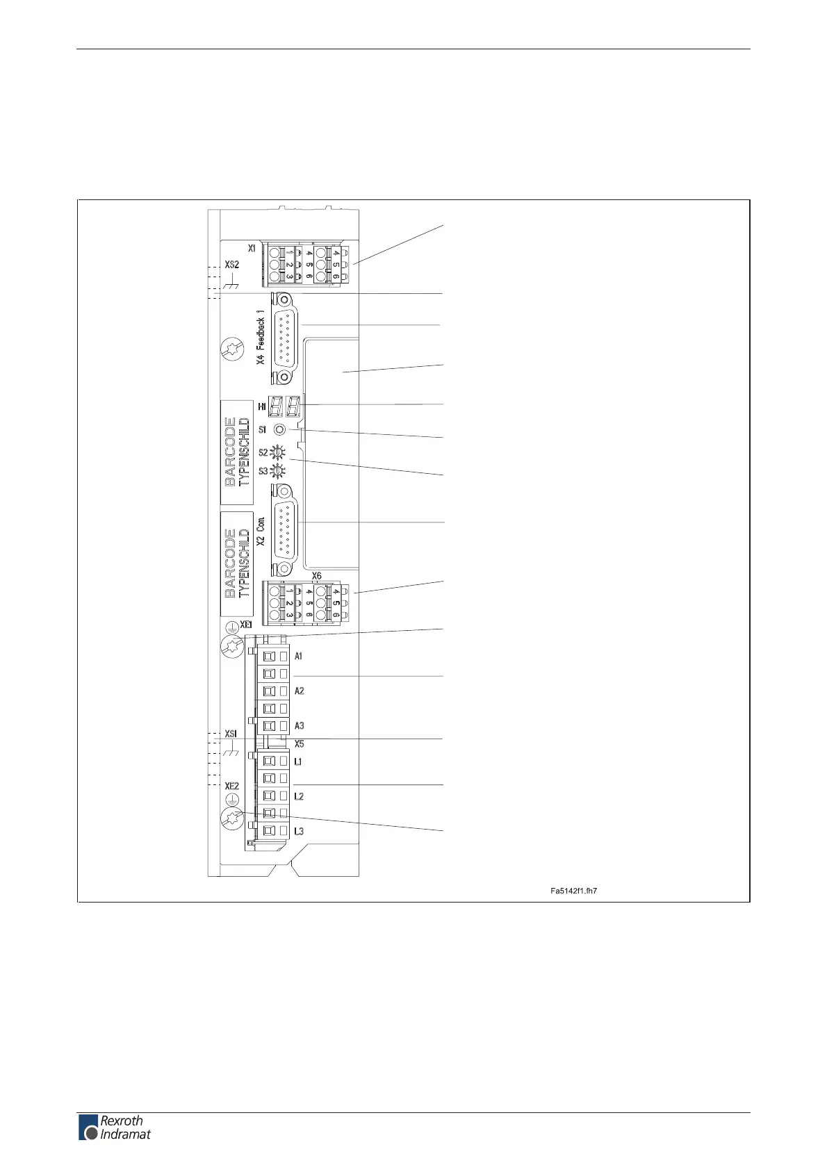
A look at the drive controller and connector designations
Front view
X2:
RS232
H1:
diagnosis indicator
S1:
fault clearance button
S2, S3:
adress switch
X4:
encoder 1
device-typical
interface
X5:
motor connection
X5:
mains connection
XS1:
holes for cable ties to x
cable shields
XS2:
holes for cable ties to x
cable shields
XE1:
protective conductor
connection (motor)
XE2:
protective conductor
connection (mains)
X1:
control voltage supply
and control signals
X6:
motor temperature monitoring
holding brake
Fig. 5-19: Front view DKC**.3-016 with connectors
customerservice@hyperdynesystems.com | (479) 422-0390

 Loading...
