610-3.**CKD 30EVIRDOCEsrellortnoC evirD 30EVIRDOCE 5-25
X3, Digital I/Os
Technical description of connector
Ap5269f1.FH7
123 4 5 6
7
9
1011 12
8
Fig. 5-35: Connector X3
Type No. of pins Design
Spring contact 2 x 6 Bushing on connector
Fig. 5-36: Design
Cross section
single wire
[mm ²]
Cross section
multi core wire
[mm ²]
Cross section
in AWG
Gauge no.:
0,2-2,5 0.2-1.5 24-16
Fig. 5-37: Connection cross section
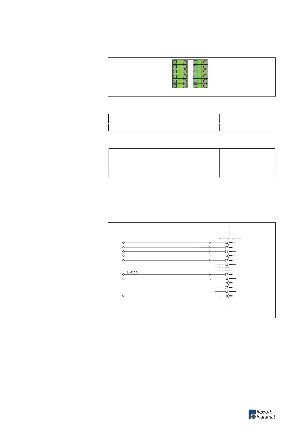
Digital Inputs (Ref, Limit+, Limit-, Cam1/ MessT1, Cam2/
MessT2, E-stop, Clear error)
AP5396f1.FH7
1
3
4
5
6
7
8
X3
9
10
11
12
2
0V
0V
0V
ext
Limit+
Limit-
Ref
Cam1 / MessT1
Cam2 / MessT2
homing switch
positive limit switch
negative limit switch
probe input 1 / cam shaft 1
probe input 2 / cam shaft 2
clear error
Clear error
E-stop
Fig. 5-38: Digital inputs
Illustration:
Design:
Connection cross section:
Connection
Digital inputs:
customerservice@hyperdynesystems.com | (479) 422-0390

 Loading...