ECODRIVE03 Drive Controllers ECODRIVE03 DKC**.040, DKC**.100, DKC**.200 4-53
X3, Digital and analog I/Os
Technical description of connector
Ap5263f1.FH7
123 4 5 6 7 8 9
10 111213141516 1718
Fig. 4-63: Connector X3
Type No. of pins Design
Spring contact 2 x 9 Bushing on connector
Fig. 4-64: Design
Cross section
single wire
[mm ²]
Cross section
multi core wire
[mm ²]
Cross section
in AWG
Gauge no.:
0,2-2,5 0.2-1.5 24-16
Fig. 4-65: Connection cross section
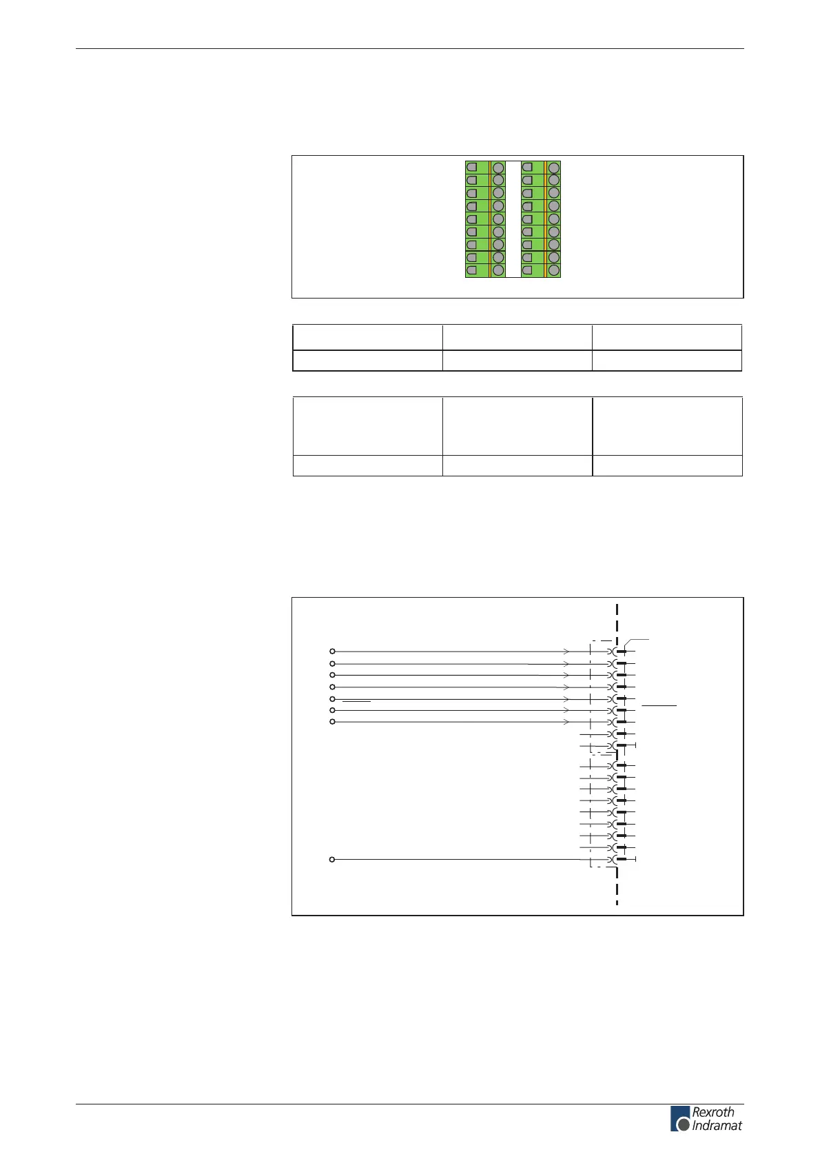
Digital Inputs (Ref, Limit+, Limit-, Cam1/ MessT1, Cam2/
MessT2, E-Stop and clear error)
AP5313F1.FH7
1
3
4
5
6
7
8
9
10
11
X3
12
13
14
15
16
17
18
2
clear error
0V
0V
E-Stop
Limit+
Limit-
Ref
Cam1 / MessT1
Cam2 / MessT2
E-Stop
0V
ext
clear error
homing switch
positive limit switch
negative limit switch
probe input 1 / cam shaft 1
probe input 2 / cam shaft 2
Fig. 4-66: Digital inputs
Illustration:
Design:
Connection cross section:
Connection
Digital inputs:
customerservice@hyperdynesystems.com | (479) 422-0390

 Loading...