ECODRIVE03 Drive Controllers ECODRIVE03 Auxiliary Bleeder Module BZM01.3 6-9
X1, Control voltage connections
Technical description of connector
Ap5264f1.FH7
123 4
567 8
Fig. 6-11: Connector X1
Type No. of pins Design
spring contact 2 x 4 bushing at connector
Fig. 6-12: Design
Cross section
single wire
[mm ²]
Cross section
multi core wire
[mm ²]
Cross section
in AWG
gauge no.:
0.2-2.5 0.2-1.5 24-16
Fig. 6-13: Connection cross section
24V control voltage supply (+24V and 0V)
AP5121F1.FH7
+24V
+24V
0V
0V
X1
2
1
3
4
5
8
7
6
device-external device-internal
connection for control voltage
connection for control voltage to additional DKCs
Fig. 6-14: Connections for control voltage
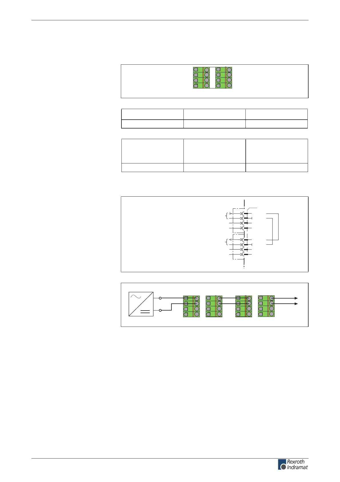
Ap5139f1.fh7
X1
X1
123 4
567 8
24V
123 4
567 8
to additional
devices
Fig. 6-15: Looping through the control voltage
Illustration:
Design:
Connection cross section:
Connection
+24V and 0V:
customerservice@hyperdynesystems.com | (479) 422-0390

 Loading...