6-10 ECODRIVE03 Auxiliary Bleeder Module BZM01.3 ECODRIVE03 Drive Controllers
Voltage at X1/1 against X1/2: see page 4-13 Control voltage
connection for DKC"
egnar egatlov dewolla aiV:noitcetorp egatlov esreveR
using internal protection
diodes
: 5-6 egap eeS:1/1X noitpmusnoc rewop ro tnerruC
"Technical data –> DC24V
voltage supply for BZM01.3"
Max. allowed current load with looping
through the control voltage via X1.1/2 to
X1.5/6:
DC 10 A
mm 1 .nim:noitces ssorc eriw ²
elbissop fi lellarap:gnituor eriw
Max. allowed inductance between 24V source
and X1:
100 µH
(equals about 2 x 75 m)
Note:
• Bleeder not available once control voltage fails.
• Control voltage failure causes the running motor to coast torque-free
(without brake).
See page 11-5: "Control Circuits with internal DC bus dynamic brake
(ZKS)"
DANGER
Dangerous movements due to unbraked
coasting of motor with control voltage failure!
Personnel should not remain within the area of the
machine with moving parts. Possible preventive
steps against unauthorized access are:
– protective fencing
– bars
– covers
– light barriers
The fences must be able to withstand the maximum
possible force that the machine can generate.
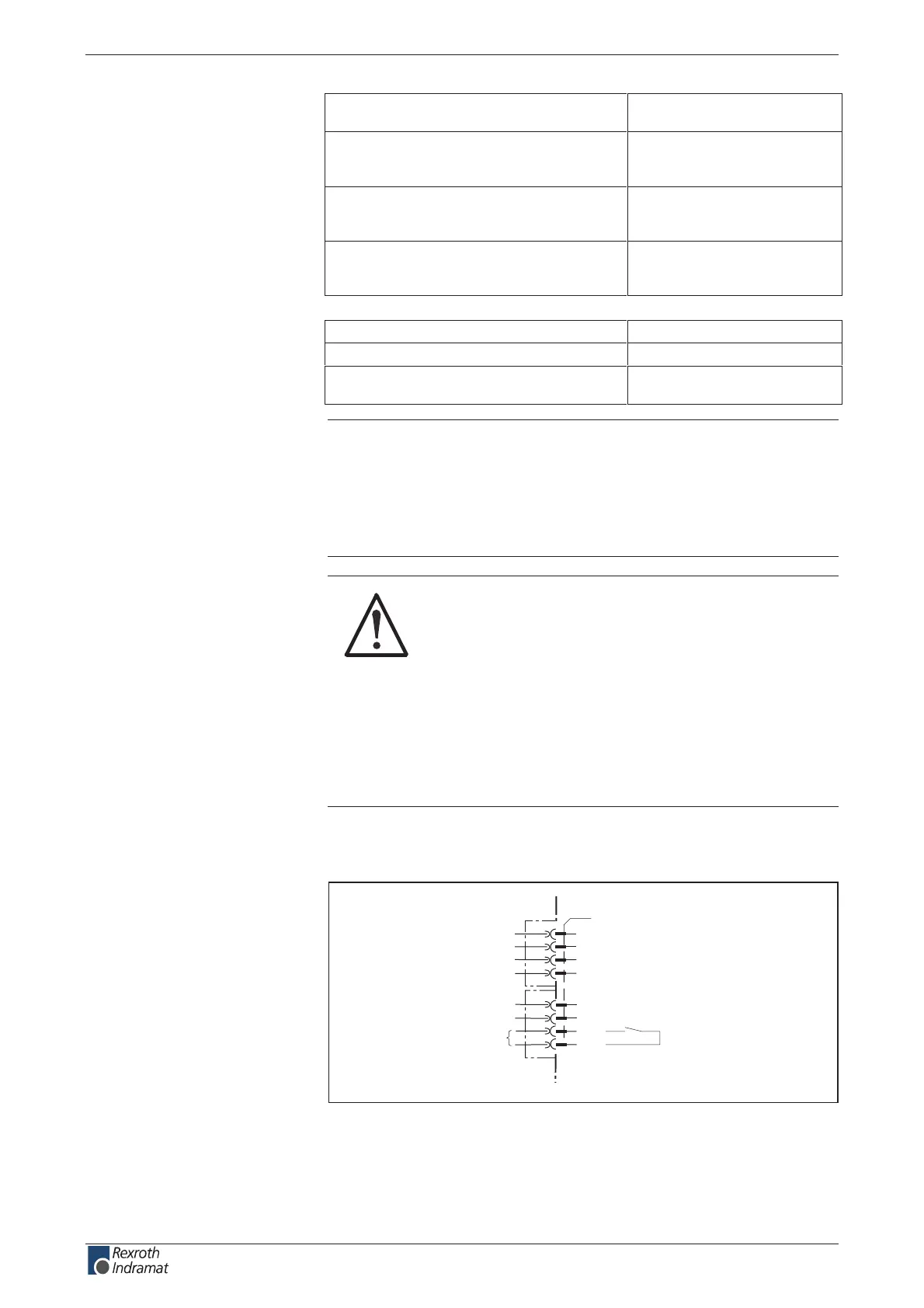
Ready to operate contact Bb
X1
2
1
3
4
5
8
7
6
Bb
Bb
ready for operation
AP5122F1.FH7
device-external device-internal
Fig. 6-16: Connections for ready to operate contact
Load capacity of connection
+24V and 0V:
wire
+24V and 0V:
Connection
Bb:
customerservice@hyperdynesystems.com | (479) 422-0390

 Loading...