ECODRIVE03 Drive Controllers ECODRIVE03 DKC**.040, DKC**.100, DKC**.200 4-59
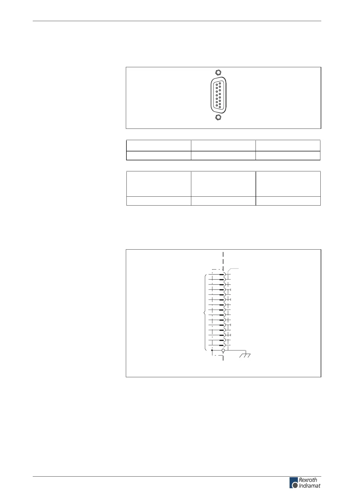
X4, Encoder 1
Technical description of connector
Ap5265f1.FH7
1
8
9
15
Fig. 4-81: Connector X4
Type No. of pins Design
D-SUB 15 bushing on unit
Fig. 4-82: Design
Cross section
single wire
[mm ²]
Cross section
multi core wire
[mm ²]
Cross section
in AWG
gauge no.:
-- 0.25-0.5 --
Fig. 4-83: Connection cross section
Encoder 1
X4
1
n.c.
2
G1Sin+
3
G1Cos+
4
0V
5
n.c.
6
0V
8
G1SDAO
9
G1Sin-
10
G1Cos-
11
0V
7
G1SCLK
12
13
0V
14
G1Sample
15
G1SDAI
G1_8V/Sin
encoder 1
AP5130F1.FH7
device-external device-internal
1) designation from the rst
ECODRIVE generation
(S3)
(S4)
(SDO)
(S1)
(S2)
(SCL)
(FS)
(SDI)
(R1)
1)
Fig. 4-84: Encoder 1
Via D-subminiature mounting screws and metal connector housing.
Clock lead for I ²C interface
Data lead for I ²C interface
Control signal for encoder initialization
Illustration:
Design:
Connection cross section:
Connection
Encoder 1:
Shield connection:
G1SCLK:
G1SDA0, G1SDAI:
G1Sample:
customerservice@hyperdynesystems.com | (479) 422-0390
 Loading...

