4-58 ECODRIVE03 DKC**.040, DKC**.100, DKC**.200 ECODRIVE03 Drive Controllers
The analog dierential inputs 1 and 2 can be parametrized as needed and
can be used, for example, as an analog speed command value inputs,
override inputs or for analog torque reduction.
See Function Description also: "Analog inputs".
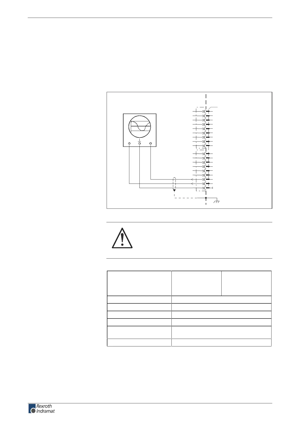
Analog outputs 1 and 2
AP5279F1.FH7
1
3
4
5
6
7
8
9
10
11
X3
12
13
14
15
16
17
18
2
for example: oscilloscope
CH1 CH2
0V
analog A2
analog A1
XS2
Fig. 4-79: Connection example of outputs A1 and A2
CAUTION
Risk of damage!
Allowed maximum cable length at X3.16 and X3.17:
3 m .
Output voltage
between A1 and 0 V:
between A2 and 0 V:
min.
- 10 V
- 10 V
max.
+ 10 V
+ 10 V
Am 2 .xamtnerruc tuptuo
R051ecnatsiser tuptuo
tiB 8retrevnoc AD
Vm 87tib rep noituloseR
short-circuit and overload
protection
not present
noitpircsed lanoitcnuf erawmrif eeSeborP
Fig. 4-80: Outputs
Analog outputs 1 and 2 can be freely parameterized and used for
diagnostics or implementation of master/slave mode.
See also rmware functional description: "Analog outputs"
Analog inputs:
Connection
Analog outputs:
Outputs
Analog outputs:
Analog outputs:
customerservice@hyperdynesystems.com | (479) 422-0390
 Loading...

