610-3.**CKD 30EVIRDOCEsrellortnoC evirD 30EVIRDOCE 5-5
tinUlobmySnoitangiseD
DKC**.3-016-7-FW
max. DC bus continuous power
for a single source supply where
U
N1
= 3 x AC 480 V, when
Ta < 45 °C
P
ZWD
6.0Wk
Prewop kaep sub CD
ZWS
see diagrams "Allowed DC bus Peak Power "
on page 5-12
noitcevnoc larutangnilooc noitces rewoP
noitcevnoc larutanrotsiser redeelb eht gnilooC
gnilooc decrof onwolf ria gnilooC
Volumetric capacity of the forced
cooling
m³/h no forced cooling
Insulation resistance at DC500V R
is
1 >mhOM
Coupling capacitance power section
against housing
C
Kop
Fn 001Fn
1)
Sine threshold value
2)
Softstart resistor is used after softstart as bleeder (R
B
).
Fig. 5-3: Technical Data DKC**.3-016-7 Mains connection and Power section
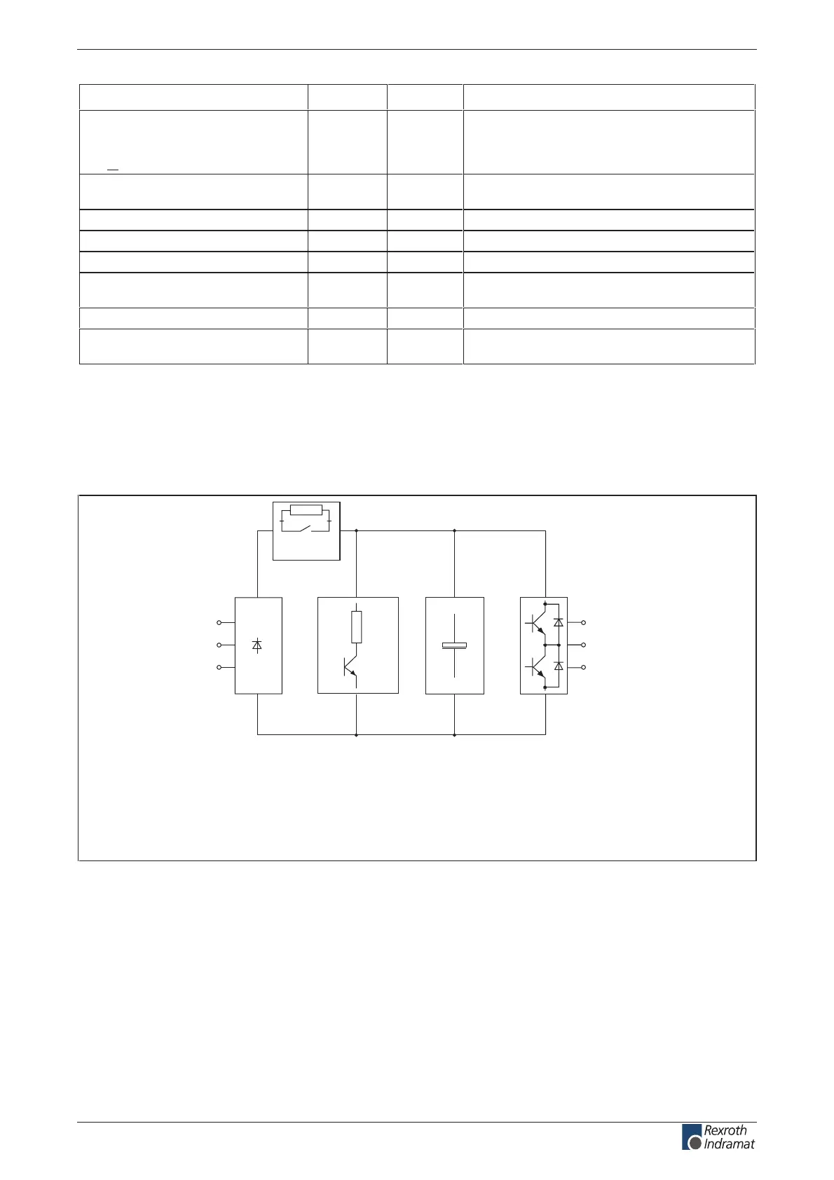
Block diagram of the DKC**.3-016-7-FW power section
R
B
C
ZW
R
Softstart
FS0217F1.FH7
A1
A2
A3
L1
L2
L3
Line input
with bridge
circuit
rectier
Bleeder circuit
DC bus
capacitance
Converter
bridge
circuit with
output to the
motor
Fig. 5-4: Block diagram of the DKC**.3-016-7-FW power section
customerservice@hyperdynesystems.com | (479) 422-0390

 Loading...