tenibaC lortnoC eht gnitcurtsnoCsrellortnoC evirD 30EVIRDOCE 12-7
Note:
• When using the signals at connectors X9, X10 and X11 maintain a
minimum distance of d = 150 mm.
• Without braking resistor power dissipation and connections at X9, X10
and X11 it is possible to reduce distance d = 80 mm .
• The minimum distance of c = 80 mm enlarges itself in dependence of
the utilized connection cables.
CAUTION
High temperature
Risk of damage to temperature-sensitive control cabinets
in the area of the cooling air outlet.
Observe the distance "d".
see also page 4-6: "Electric Data of the Individual DKC**.3 Components"
and page 6-3: "Electrical data of auxiliary component BZM01.3".
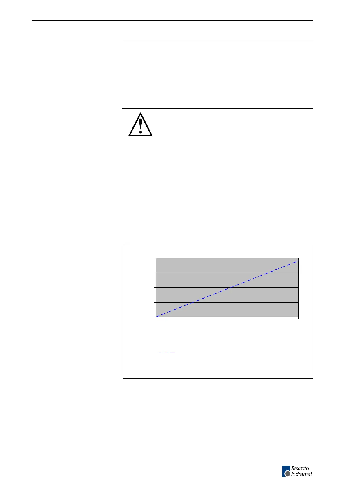
Note: Diagram "Temperature increase via continuous braking
resistor power" shows the relationship between braking
resistor load and temperature of cooling air entering at unit
underside and exiting top side under nominal current
conditions of the controller.
0
10
20
30
40
050
Continuous bleeder power PBD in W
Temperature increase in K
Temperature increase in K for d~80mm
Fig. 12-11: Temperature increase DKC**.3-016-7-FW
Volumetric capacity of the
forced cooling
DKC**.3-016-7-FW
customerservice@hyperdynesystems.com | (479) 422-0390

 Loading...