11-6 srellortnoC evirD 30EVIRDOCEsnoitcennoC sniaM
Ap5311f1.fh7
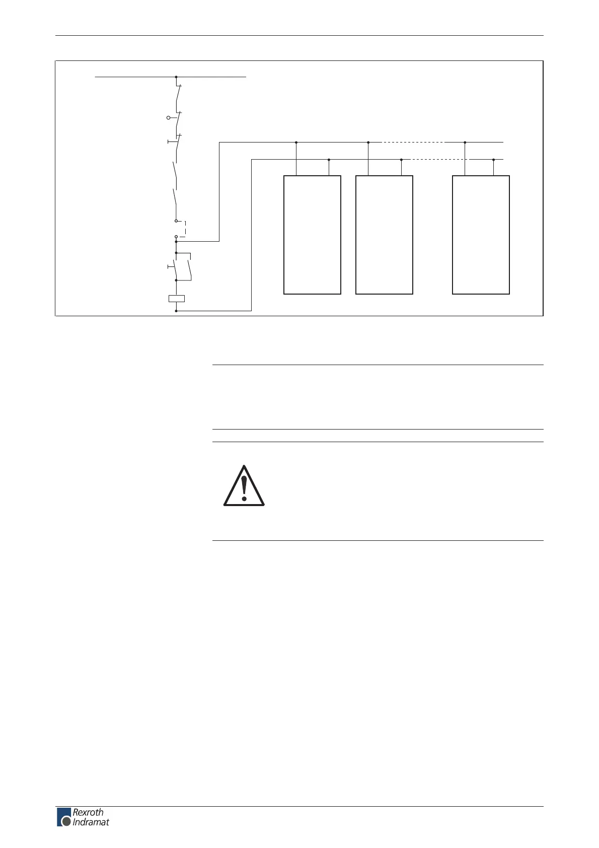
Interface unit of internal
DC bus dynamic braking circuit
K1
1)
K1
Bb
3)
Power o
Power on
Control error
message
Power protection
ext. control voltage +DC 24 V
Safety limit switch
Emergency stop
ZKS1
DKC
BZM
ZKS1
DKC
BZM
ZKS1
DKC
BZM
ZKS2ZKS2ZKS2
1): Integrate Bb contacts of more drive controllers and BZM**.* in series.
3): Switching power of Bb contact must be noted.
Fig. 11-3: Example of generating the DC ZKS signal
Note: All ZKS setups are controlled parallel on shared DC bus loop!
Any delay in the drop out of the main contactor also causes a
delay in the activation of the ZKS function.
=> See page 11-12: "Q1 Fuse and K1 Contactor".
CAUTION
Danger of damage!
If as a result of the application a manual actuation of
the load contactor K1 is necessary then the built in
DC bus dynamic brake setups must be protected by
applying switched mains voltage to the mains
connecting terminals of the DKC and BZM units in
use.
customerservice@hyperdynesystems.com | (479) 422-0390

 Loading...