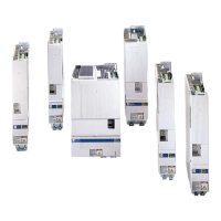
16-30 srellortnoC evirD 30EVIRDOCEtnemhcattA
Explanation of Chronological Sequence
"Control voltage applied"
DC24V – supply at X1
"Bb contact closed"
Bb contact in DKC**.3 on X1
"Mains voltage applied"
Power supply at X5,
Start of DC bus charge procedure
"U
d
- Signal"
Signal output at X3
(not for DKC**.3-016)
"RF applied"
Signal drive enable applied by user.
"Actual brake contact"
Brake contact in DKC**.3 on X6 is triggered.
Brake contact parameterized as N/C or N/O (see rmware functional
description)
"Motor brake released"
Brake controlled via motor contact has been released.
"
AH applied"
Signal
AH (start signal at X1 (see rmware functional description).
"
AH is working internally"
Internal signal sequence depends on motor used.
customerservice@hyperdynesystems.com | (479) 422-0390

 Loading...


