ECODRIVE03 Drive Controllers ECODRIVE03 DKC**.040, DKC**.100, DKC**.200 4-47
Drive halt (AH) and Drive enable (RF)
Note:
• Inputs work with inactive bus communication.
• Inputs don ’t work with active bus communication (SERCOS interface,
Probus-DP, ...).
AP5270F1.FH7
AH
drive halt
RF
drive enable
X1
2
1
3
4
5
8
7
6
device-external device-internal
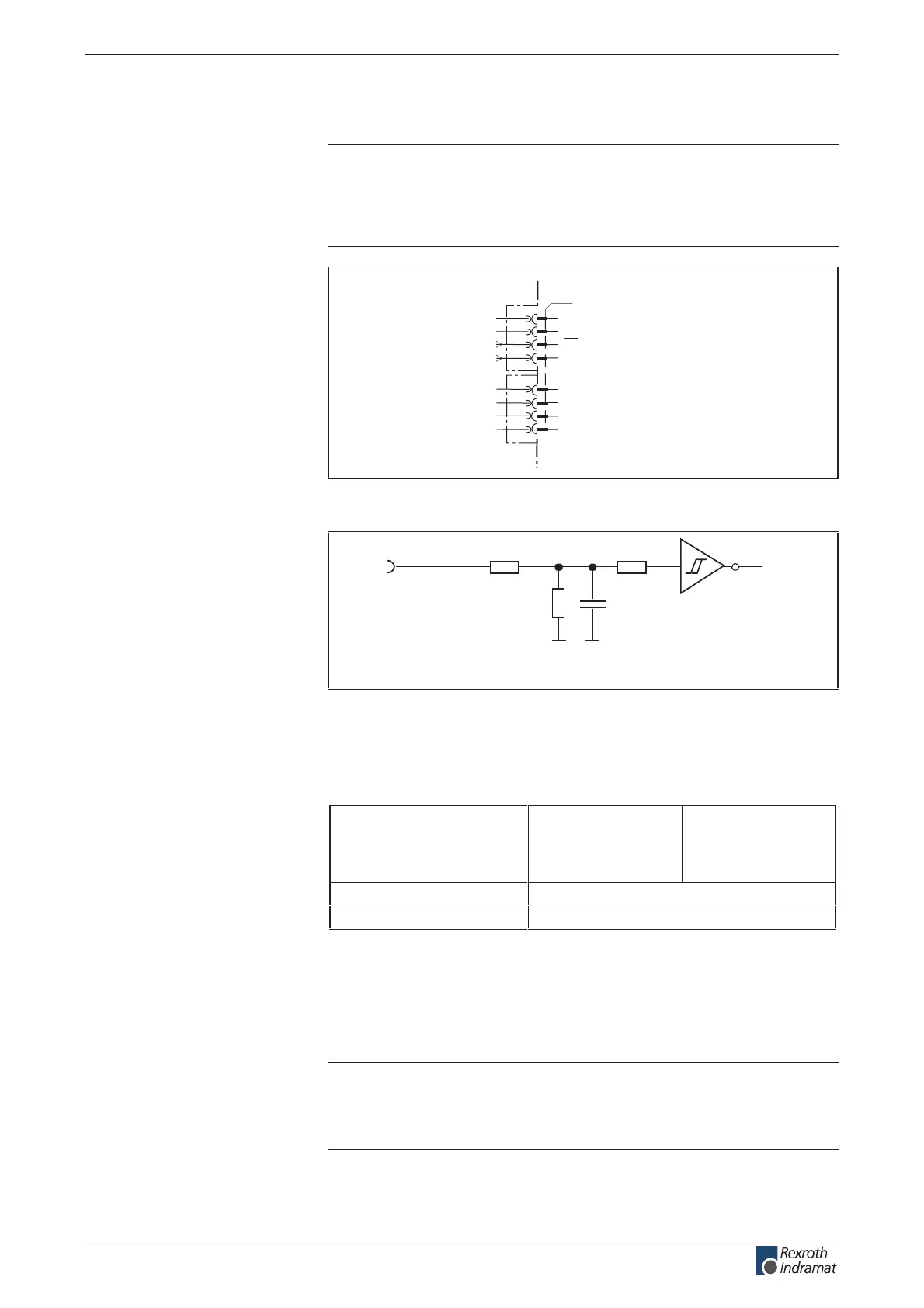
Fig. 4-53: Connections for drive halt and drive enable
R1 R3
R2
C1
I
n
Ap5183f1.fh7
Schematics
R1: 10k
R2: 3k3
R3: 10k
C1: no data
Fig. 4-54: Input circuit
Input voltage:
High
Low
min.
16 V
-0.5 V
max.
30 V
3 V
%5 ± mhOk 3.31ecnatsiser tupnI
noitpircsed lanoitcnuf erawmrif eeSemit noitcaeR
Fig. 4-55: Inputs
The drive halt function is used to bring an axis to standstill with dened
acceleration and jerk (see rmware functional description).
The input drive enable (RF) activates the drive with a 0-1 edge.
Note: If the inputs are controlled by a power supply other than the
DC24 volt supply of the drive controller, then the reference
lead of the other power supply must be connected to X1.2
(0 V).
Connection
AH and RF:
Input circuit
AH and RF:
Inputs
AH and RF:
AH:
RF:
customerservice@hyperdynesystems.com | (479) 422-0390

 Loading...