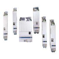
4-56 ECODRIVE03 DKC**.040, DKC**.100, DKC**.200 ECODRIVE03 Drive Controllers
Depending on operating mode and parameter programming a number of
monitoring functions are conducted. If a condition is detected that still
allows for correct operations but would eventually lead to an error, then
the warning is set to high.
See also rmware functional description.
If the unit is ready for the drive enable, then the output ready is set to
high.
The output is set to low
• with a pending error
• with DC bus voltage < (0.75 x threshold value of applied mains
voltage)
• with lacking control voltage
See also functional rmware description: "Ready".
Once the minimum voltage in the power DC bus is reached, then th
e
controller is ready to output power and the U
D
output is set to high. Signal
U
D
-message has a special meaning for "central supply" whereby it
supplies input U
D power
supply
.
See page 4-88: "UD power supply".
Delay time t
d
from applying mains voltage to the setting of the U
D
signal is
• single phase mains connection:
ms503*C*2.1*R*2t ZWsoftstartd +=
t
d
delay time
R
Softstart
take value from "technical data" list
Czw: sum of DC bus capacitors
Fig. 4-72: Delay time for single phase mode
See page 4-36: "Allowed DC bus continuous power with single-phase
mains connection".
• three-phase main connection:
ms503*C*2.1*Rt ZWsoftstartd +=
Fig. 4-73: Delay time for three-phase mode
This resistance of all mains voltages connected to DKC at one DC bus
softstartnsoftstart2softstart1 R
1
.....
R
1
R
1
R
1
+++=
Fig. 4-74: Load resistance
The resulting DC bus capacitance of all units on one DC bus
CZMZW,DKCnZW,DKC2ZW,DKC1ZW, CC...CCC ++++=
Fig. 4-75: DC bus capacitance
Warnings:
Ready:
U
D
-message:
Resulting load resistance R:
Resulting DC bus capacitance C:
customerservice@hyperdynesystems.com | (479) 422-0390

 Loading...


