• Correction can be disabled with SP2-927.
How Correction is Made
Immediately after creating the ID sensor pattern [A] used for toner density control (* "Toner Density
Control"), the machine generates another pattern [B] for charge voltage correction by intensifying the
development bias (* "Development Bias") to –600 V. The laser remains off, but a small amount of toner
moves to the drum because of the slight charge difference between the drum and development roller. The
ID measures the pattern's density (Vsdp) and the bare drum voltage (Vsg); the FCU compares the difference
and adjusts the roller voltage accordingly.
• If Vsdp/Vsg > 0.95: Change charge roller voltage by +50 V (less negative).
• If Vsdp/Vsg < 0.90 = Change charge roller voltage by –50 V (more negative).
• The current ID sensor readings can be viewed using SP2-221.
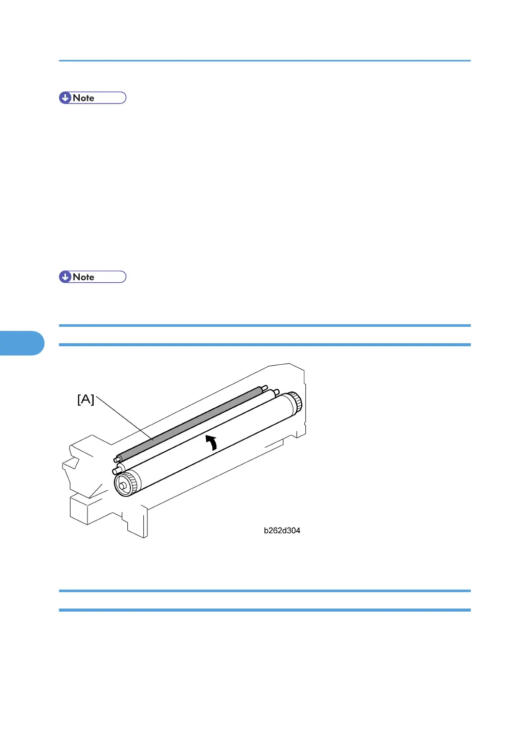
Charge Roller Cleaning
A cleaning roller [A] removes toner and debris that the roller picks up from the drum.
Detection of New PCU
Before starting to use a new PCU, the machine must (a) agitate the toner/developer mix, (b) initialize the
TD sensor, and (c) initialize the PCU counter. This machine automatically detects the presence of a new
PCU and carries out these operations.
6. Detailed Section Descriptions
264
 Loading...