ODIN Intercom Matrix Menu System Description 125
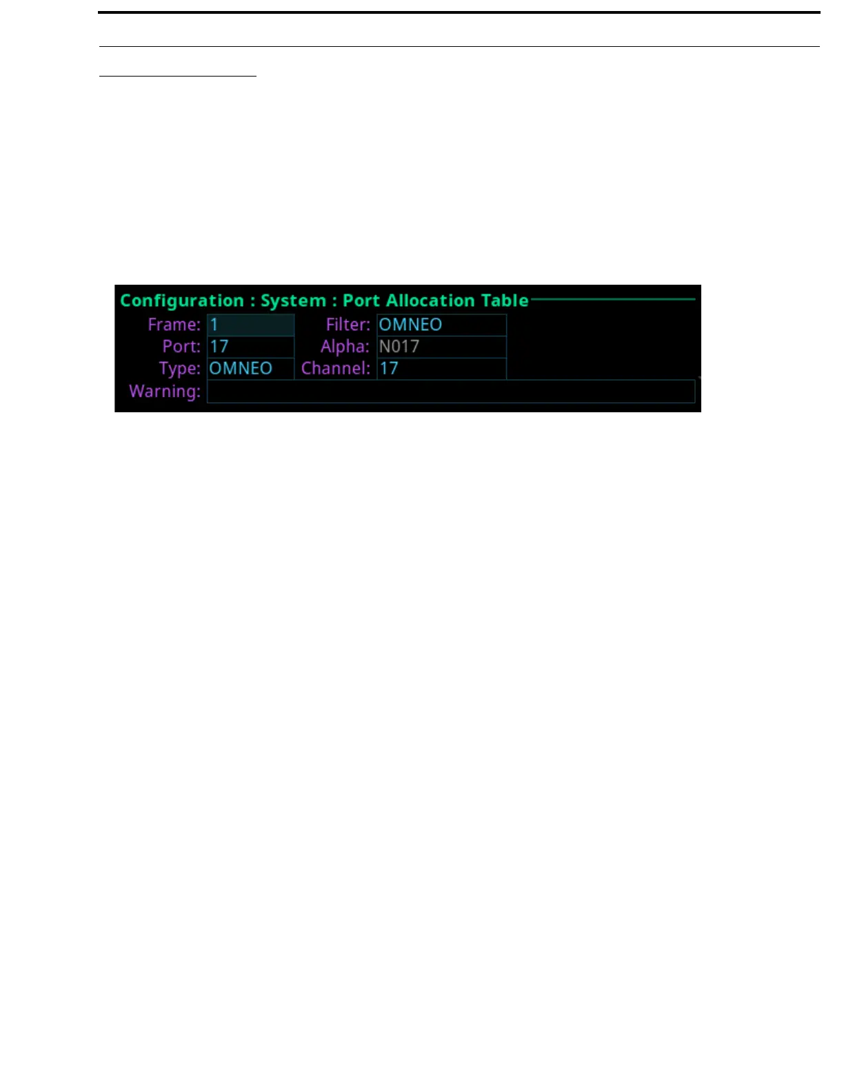
Port Allocation Table
The Port Allocation Table is used to allocate the different types of intercom port assignments across the intercom system. Physical
hardware, such as AIO and 2-wire devices, and network port devices, such as OMNEO, can be mapped to any port in the intercom.
For detailed instructions on how to allocate ports, see “Intercom Port Allocation” on page 38.
The default port allocations are:
Ports 1 – 14 are AIO, mapped to the physical AIO connectors (J4).
Ports 15 & 16 are 2-Wire, mapped to the physical XLR connectors CH-A and CH-B.
Ports 17 and higher (if licensed) are OMNEO.
Frame Field
The Frame field is used to select the frame to be viewed.
Port Field
The Port field is used to select the port to configure.
Type Field
The Type field is used to select the port type to configure.
Available options are None, 2W, AIO, OMNEO, RVON.
Filter Field
The Filter field is used filter on the type of port. For example, filtering on AIO displays only AIO configured ports.
Available options are None, 2W, AIO, OMNEO, and RVON.
Alpha Field
The Alpha field displays the Alpha assigned to the selected port.
Channel Field
The Channel field is used to map AIO and 2W port instances to the physical hardware ports on the back of the frame. For instance,
intercom port 5 may be assigned a port of AIO and an AIO channel 1. This means intercom port 5 must be mapped to the first AIO
connector on the back of the frame.
Warning Field
The Warning field displays if a port has an invalid configuration. For example, if too many AIO or 2W ports are assigned or if the
same AIO or 2W channel is assigned to more than one port.
FIGURE 54. Configuration | System | Port Allocation Table