14 Introduction ODIN Intercom Matrix
Connections
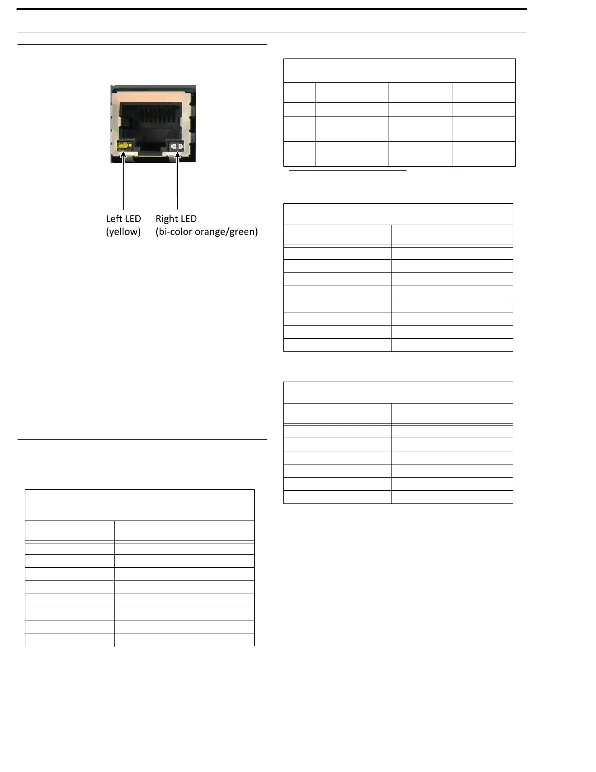
RJ-45 Ethernet
Connectors
Use the Ethernet
connector to
connect ODIN to a
network. Each RJ-
45 Ethernet
connector has two
LEDs:
Left LED. The left
LED is yellow and
indicates a network
link is established. It
flashes on/off whenever there is network activity.
Right LED. The right LED is bi-color (orange and green) and
indicates the speed of the connection by the color displayed.
• A green LED indicates the port is operating at
1000Mbps (1 Gbps). This is suitable for OMNEO
networking.
• An orange LED indicates the port is operating at
100Mbps.
• No LED color indicates the port is operating at
10Mbps. This is not suitable for OMNEO nor
RVON networking.
Connector Pinouts
Front Panel Connector
Rear Panel Connectors
Management Port - RJ-45
Supports 10/100/1000 Ethernet
Pin Assignment
1 Data 1 +
2 Data 1 -
3 Data 2 +
4 Data 3 +
5 Data 3 -
6 Data 2-
7 Data 4+
8 Data 4-
2W Party Line: J1 & J2
a
a. ODIN does not supply power.
Pin RTS Audiocom Clear-Com
1 GND GND GND
2 RTS CH1 (+30 V) Audio Hi
(+24 V)
(+30 V)
3RTS CH2
(Optional +30 V)
Audio Low
(+24 V)
Audio
AIO Connector (RJ-45): J4 - x16
Pin Assignment
1
Data +
2 Data -
3Audio Out +
4 Audio In +
5 Audio In -
6Audio Out -
7 Data +
8 Data -
AIO Connector (RJ-12): J4 - x16
Pin Assignment
1
Data -
2Audio Out +
3 Audio In +
2 Audio In -
3Audio Out -
6 Data +