ODIN Intercom Matrix Menu System Description 95
Mode Field
The Mode field displays the operating mode of the channel.
Available modes are:
Signal Field
The Signal field displays whether a signal has been detected on the 2-wire port.
Signals displayed are: Mic Kill, Setup, Call, and DC Call.
Audio Field
The Audio field displays a real-time VU Meter (audio signal strength) for each port. The segmented bar graph is used to show
audio is present on the port and the strength of the audio.Audio signals below -6 dB are shown in green, while signals between
-6 dB and 0 dB are shown in yellow and signals greater than 0 dB are shown in red.
PWR Field
The PWR field indicates whether ODIN detects DC Power (for example, voltage) on the 2W line. In most systems, there is a
power supply like a PS-20 on the 2W line which provides power to the beltpacks. This status indication could be useful to ensure
that their system is set up correctly.
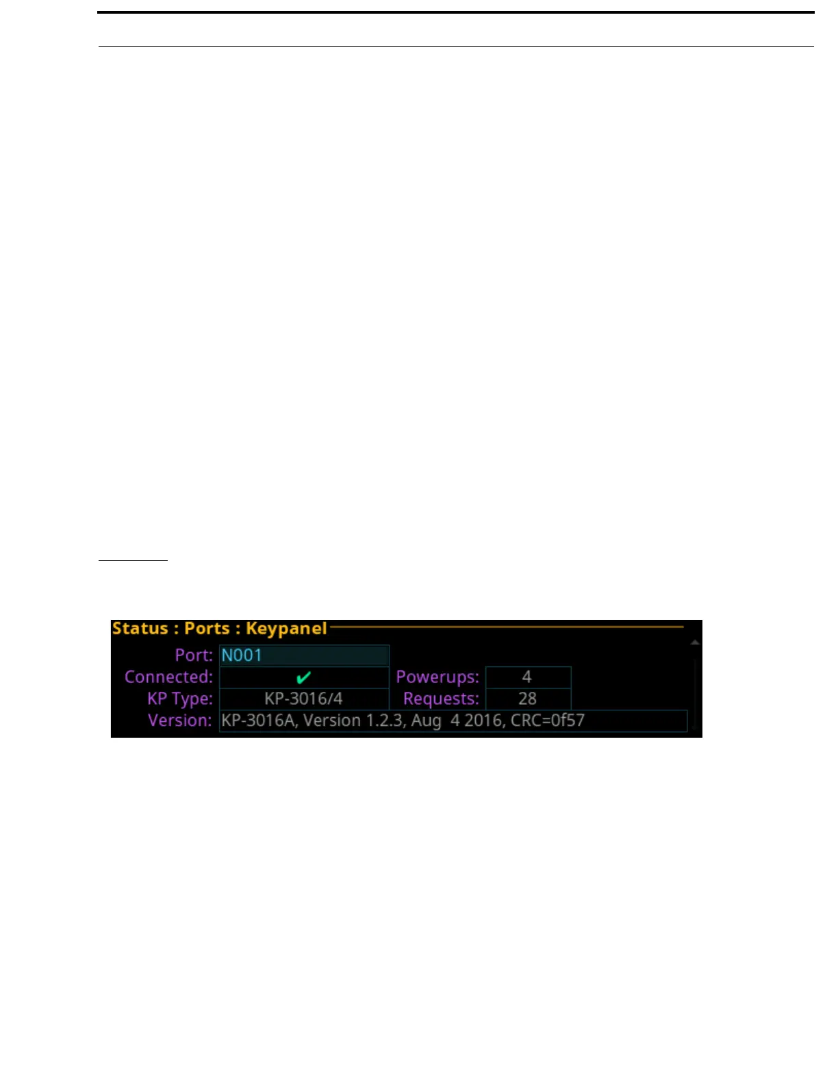
Keypanel
The Keypanel screen is used to view the status information of connected keypanels.
Port Field
The Port field is used to select the port to view.
Off No modes are active
RTS 1 RTS Channel 1 Mode
RTS 2 RTS Channel 2 Mode
Audiocom Audiocom Mode (balanced)
Clear-Com ClearCom Mode (unbalanced with DC call)
FIGURE 27. Status | Ports | Keypanel