12 Introduction ODIN Intercom Matrix
Specifications
Power Supply:
Type .................................Locking IEC 320 C14 style connector
(2 connectors, fully redundant
load-sharing power supplies)
AC Input. ...................................................100 VAC – 240 VAC,
60/50 Hz, 0.5 A / 0.35 A
Maximum
Power Consumption...........................47 W (based on 120 VA C )
NOTE: Lighted power buttons on front panel control DC
voltage feed to internal circuitry; they do not
disconnect AC from the internal power supplies.
Power cords must be fully removed from frame to
safely disengage internal power.
Environmental:
Operating Temperature .................32° F – 113° F (0° C – 45° C)
Storage Temperature..................-4° F – 158° F (-20° C – 70° C)
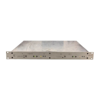
Dimensions:
19" w/ rack ears (17.3" w/o rack ears) W x 1.7" H x 14.3" D
(including connectors)
(482.6 mm w/ rack ears [439 mm w/o rack ears] W x 43.7 mm H
x 363.5 mm D [including connectors])
Weight:
ODIN Frame ..................................................... 11.5 lbs (5.2 kg)
Optional Mounting Bracket ........................ 0.86 lbs (390 grams)
AIO 4-Wire Analog:
Connectors .................................................. 16 RJ-45 connectors
Signal Format..............................Differential RX/TX audio with
differential RS-485 control data
Wiring Scheme .......................... Both 568B & USOC supported
A/D and D/A Resolution ...................................................24 bits
Max Input
Level (balanced) ....................................... +20 dBu w/o clipping
Digital
Input Gain ............................. Programmable (-20 dB to +20 dB)
Input
Frequency Response
+1 dB/-3 dB from 100 Hz to +20 kHz
THD+N
(8dBu input, unity gain)...............0.025% non-weighted@1 kHz
<0.075% non-weighted,
100 Hz to +20 kHz
Nominal Input Impedance ............................................... >22 kΩ
Nominal Output Level ........................................................8 dBu
Digital Output
Gain....................................... Programmable (-20 dB to +20 dB)
Maximum Output
Level (balanced) @ 600 Ohms ....................20 dBu w/o clipping
Output
Frequency Response
+1 dB / -3 dB from 100 Hz to +20 kHz
Output Noise Floor ....................................................... <-70 dBu
Crosstalk Isolation ........................................................... >80 dB
2-Wire Party Line Analog:
Connector ..............................two 3-pin female XLR connectors
Modes/Port supported................................. RTS CH1, RTS CH2
Audiocom (1 channel)
Clear-Com (1 channel)
4W/2W Echo Return Loss................................................>45 dB
Unbalanced Operation (RTS/Clear-Com)
Expected Termination Impedance ......................................200 Ω
Noise Contribution ....................................................... <-70 dBu
THD+N (w/ nominal input)................<0.5%, 200 Hz to 7.3 kHz
Bridging Impedance ........................................................ >10 kΩ
CALL Signaling .......................................... 20 kHz (RTS mode)
12 VDC (Clear-Com mode)
MIC KILL Signaling .................................. 24 kHz (RTS mode)
Balanced Operation (Audiocom)
Expected Termination Impedance ......................................300 Ω
Noise Contribution ....................................................... <-70 dBu
THD+N
(with nominal input)...........................<0.5%, 200 Hz to 7.3 kHz
Bridging Impedance ........................................................ >10 kΩ
CALL Signaling .................................20 kHz (Audiocom mode)
MIC KILL Signaling ..........................24 kHz (Audiocom mode)
General Purpose Input/Output Ports:
Relays
Type ....................................................................................SPDT
Contacts .................................................................. Common (C)
Normally Closed (NC)
Normally Open (NO)
Contact Rating......................................................1A @ 48 VDC
Inputs
Type ................................................................ Optically Coupled
Input Voltage ...................................... 5 VDC to 12 VDC on A+
NOTE: A+ is internally pulled to +5 VDC. Connect K-to
chassis ground to activate.
1
PAP/LCP/GPIO Port:
Connector ........................................................................... RJ-45
Format ................................RS-485 control data only (no audio)
Inter-Frame Link Port (2 UPLINK/2 DOWNLINK):
NOTE: Supports expansion and connection of up to eight
ODIN frames.
Fiber Connector Type.................................... Small Form Factor
Pluggable (SFP)
Multimode .......................................... Finisar FTLF8519P3BNL
500 m / 2.125 Gbps
Single Mode ....................................... Finisar FTLF1421P1BTL
15 km / 2.67 Gbps
Speed ................................................................................ 2 Gbps
LED Indicator...........................................Optical Signal Present
NOTE: SFF-8472 fiber diagnostics supported
1. Only used for PAP-32 devices, not PAP-5032 devices.