EasyManuals Logo

SATO E series Service Manual

SATO E series
206 pages
To Next Page IconTo Next Page
To Previous Page IconTo Previous Page
Page #113 background imageLoading...
Page #113 background image
PN 9001098
Rev. A
6-9
SATO M-10e TT/DT Printers Service Manual
Section 6. Replacement Procedures
STEP PROCEDURE
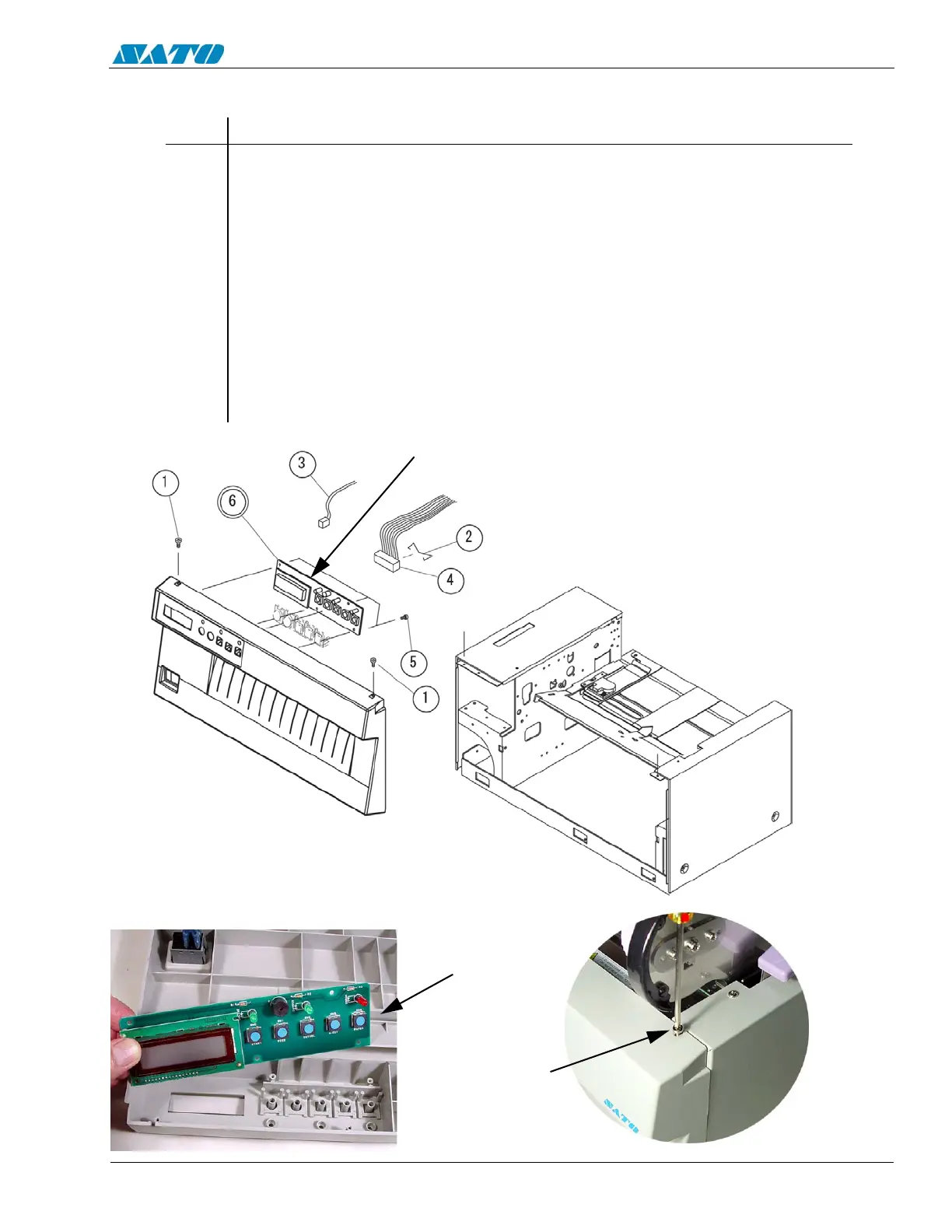
1. Switch the printer OFF and disconnect the power cord.
2. Remove (2) Item 1 screws from top of front cover. Lift up cover to detach it
from slots.
3. Remove Item 2 Connector Lock and detach Item 3 and 4 Connectors.
4. Remove (4) Item 5 screws and remove Item 6 LC/Keyboard PCB from front
cover.
5. Replace the LC/Keyboard PCB.
6. Reattach connectors.
7. Replace the front cover.
6.7 Replacing the LC/Keyboard PCB
LC/KEYBOARD
PCB
REMOVE (2)
SCREWS
REMOVE
LC/KEYBOARD
PCB

Table of Contents

Other manuals for SATO E series

Questions and Answers:

Question and Answer IconNeed help?

Do you have a question about the SATO E series and is the answer not in the manual?

SATO E series Specifications

General IconGeneral
Print MethodThermal Transfer / Direct Thermal
Max. Print Speed6 ips (inches per second)
Max. Print Width4.09 inches (104 mm)
InterfacesUSB, Ethernet
Media TypeLabels, Tags, Ticket
Ribbon LengthUp to 984 ft (300 m)
Power SupplyAC 100-240V, 50/60 Hz
Print Resolution203 dpi

Related product manuals