PN 9001098
Rev. A
6-13
SATO M-10e TT/DT Printers Service Manual
Section 6. Replacement Procedures
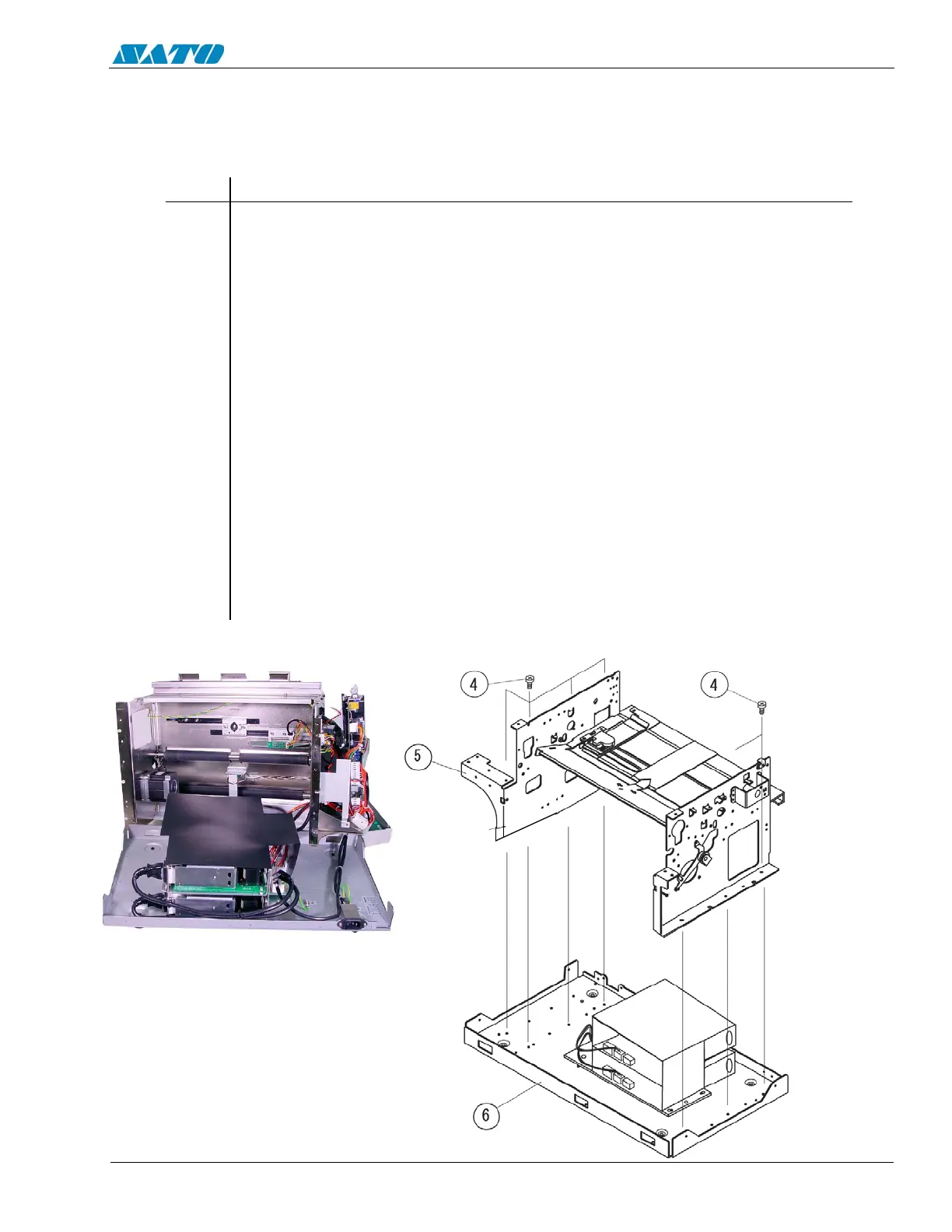
6.10 Replacing the Power Supply
STEP PROCEDURE
1. Switch the printer OFF and disconnect the power cord.
2. Refer to Section 6.2 and remove the covers.
3. Refer to illustrations on pages 6-13 and 6-14.
Remove (7) Item 4 screws to detach the main chassis from the base.
4. Peel back and detach Item 1 Power Supply Cover.
5. Detach all cable connections to the power supply.
6. Remove (7) Item 2 screws holding the power supply to the base.
7. Remove and replace the defective power supply.
8. Reattach the power supply to the base.
9. Reattach the cable connections and the Power Supply Cover.
10. Reattach the base to the main chassis.
11. Replace the covers.
12. Check the DC power voltages. Refer to Section 4.3.
The Power Supply is a non-repairable component with no servicable parts and is to be
replaced as a complete assembly.
DETACH THE MAIN CHASSIS
FROM THE BASE

 Loading...


