EasyManuals Logo

SATO E series Service Manual

SATO E series
206 pages
To Next Page IconTo Next Page
To Previous Page IconTo Previous Page
Page #124 background imageLoading...
Page #124 background image
SATO M-10e TT/DT Printers Service Manual
PN 900109
Rev. A
6-20
Section 6. Replacement Procedures
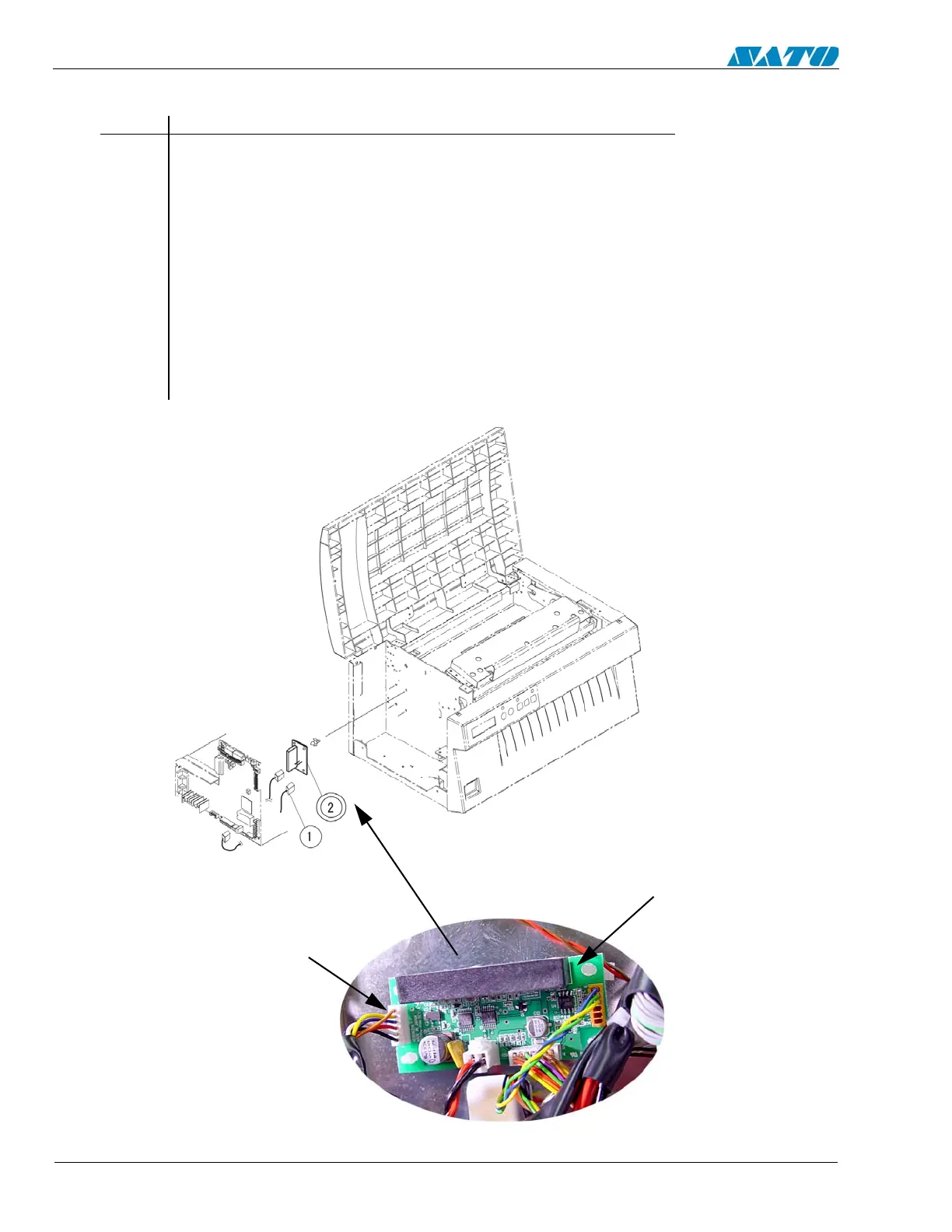
6.14 Replacing the Ribbon PCB
STEP PROCEDURE
1. Switch the printer OFF and disconnect the power cord.
2. Refer to Section 6.9 and remove the Interface PCB if installed.
3. Refer to Section 6.8 and remove the Main Circuit Board.
4. Detach the Item 1 Connectors.
5. Remove and replace Item 2 RBM PCB set.
6. Replace the Main Circuit Board.
7. Replace the left side cover.
8. Complete the Factory Reset Procedure.
DETACH ITEM 1
CONNECTORS
REMOVE AND
REPLACE ITEM 2
RBM PCB

Table of Contents

Other manuals for SATO E series

Questions and Answers:

Question and Answer IconNeed help?

Do you have a question about the SATO E series and is the answer not in the manual?

SATO E series Specifications

General IconGeneral
Print MethodThermal Transfer / Direct Thermal
Max. Print Speed6 ips (inches per second)
Max. Print Width4.09 inches (104 mm)
InterfacesUSB, Ethernet
Media TypeLabels, Tags, Ticket
Ribbon LengthUp to 984 ft (300 m)
Power SupplyAC 100-240V, 50/60 Hz
Print Resolution203 dpi

Related product manuals