EasyManuals Logo

SATO E series Service Manual

SATO E series
206 pages
To Next Page IconTo Next Page
To Previous Page IconTo Previous Page
Page #125 background imageLoading...
Page #125 background image
PN 9001098
Rev. A
6-21
SATO M-10e TT/DT Printers Service Manual
Section 6. Replacement Procedures
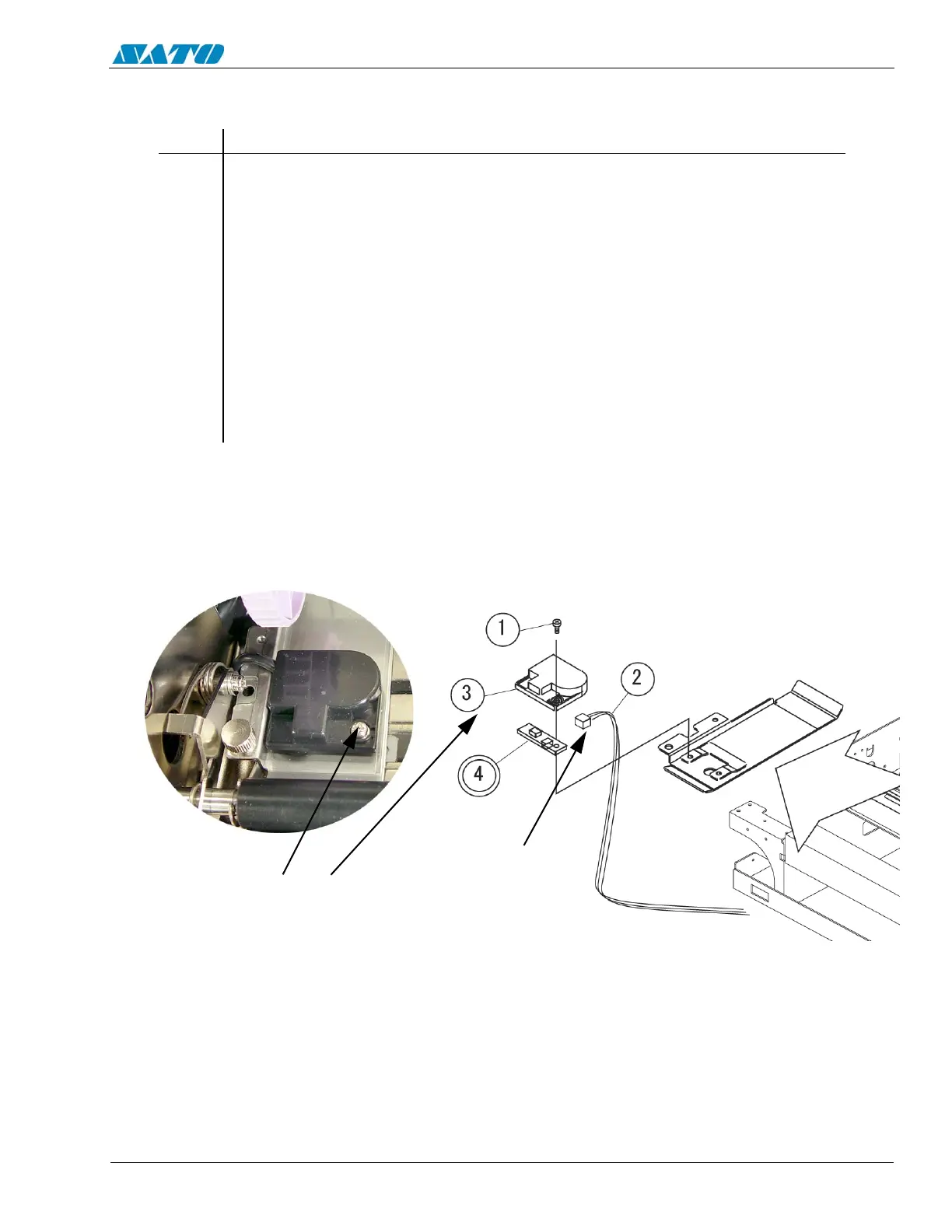
6.15a Replacing the Pitch Sensor (SEN2 PCB) (Gap Sensor)
STEP PROCEDURE
1. Switch the printer OFF and disconnect the power cord.
2. Raise the Access Cover.
3. Unload the ribbon and label stock. (NA for ribbon on Direct Thermal units).
4. Remove (1) Item 1 screw to detach Item 3 Sensor Cover from SEN2 PCB.
5. Detach (1) Item 2 connector from Item 4 SEN2 PCB.
6. Remove and replace SEN2 PCB.
7. Replace the Sensor Cover.
8. Refer to Section 4.6 “Adjustment of Gap Sensor”.
SEN2
REMOVE ITEM 1
SCREW TO DETACH
ITEM 3 SENSOR
COVER FROM ITEM 4
SEN2 PCB
DETACH ITEM 2
CONNECTOR

Table of Contents

Other manuals for SATO E series

Questions and Answers:

Question and Answer IconNeed help?

Do you have a question about the SATO E series and is the answer not in the manual?

SATO E series Specifications

General IconGeneral
Print MethodThermal Transfer / Direct Thermal
Max. Print Speed6 ips (inches per second)
Max. Print Width4.09 inches (104 mm)
InterfacesUSB, Ethernet
Media TypeLabels, Tags, Ticket
Ribbon LengthUp to 984 ft (300 m)
Power SupplyAC 100-240V, 50/60 Hz
Print Resolution203 dpi

Related product manuals