PN 9001098
Rev. A
6-23
SATO M-10e TT/DT Printers Service Manual
Section 6. Replacement Procedures
STEP PROCEDURE
1. Switch the printer OFF and disconnect the power cord.
2. Remove the Front Cover. Refer to Section 6.7 Replacing the LC/Keyboard PCB.
3. Remove the Cutter or Tear-off cutter. Refer to Section 6.18 Replacing the Cutter Unit.
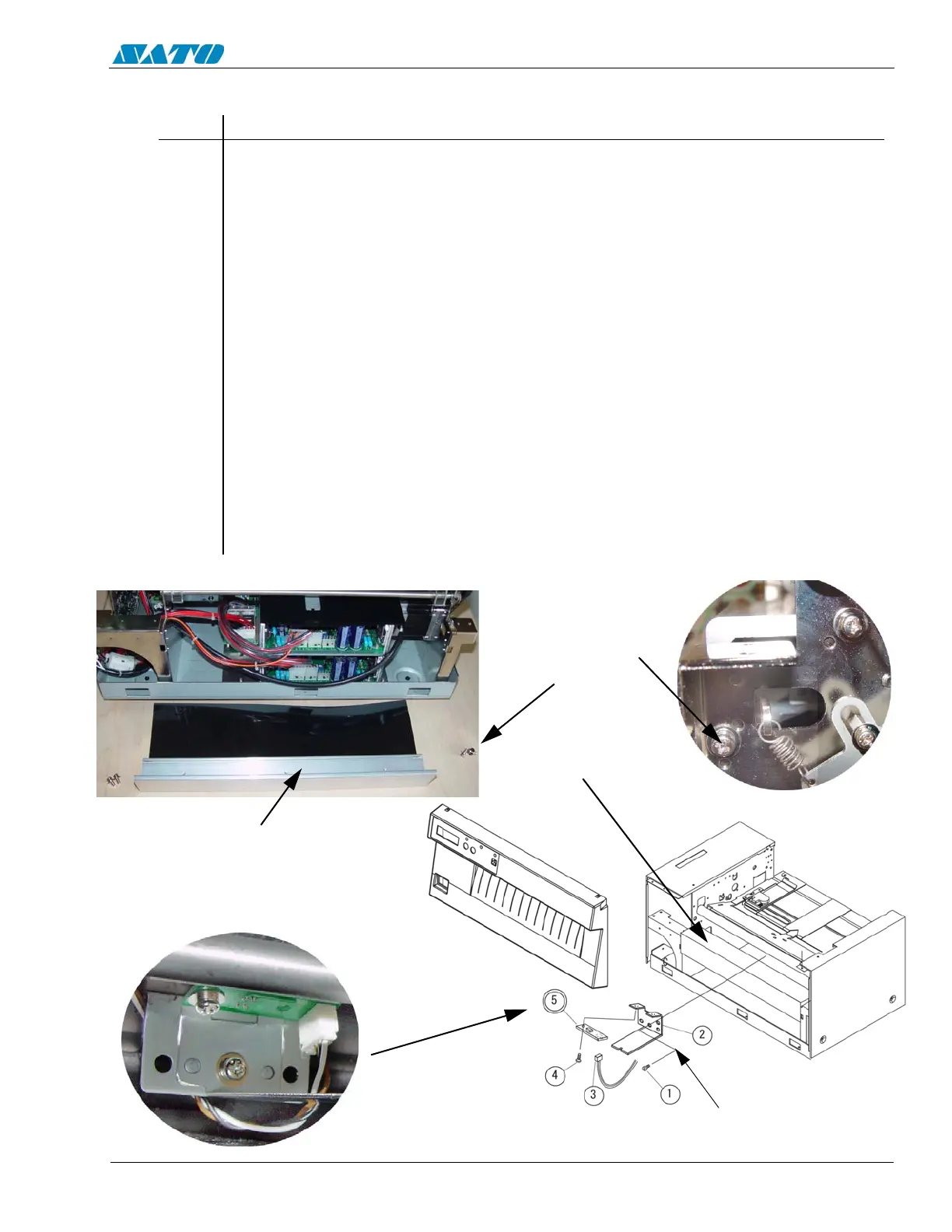
4. Remove (2) screws from both sides of Stay. Detach the Stay.
5. Detach the Item 3 connector.
6. Remove (1) Item 1 screw from Item 2 Sensor Bracket.
7. Remove (1) Item 4 screw to detach Item 5 Sensor from Item 2 Sensor bracket.
8. Remove and replace the sensor.
9. Reattach Item 3 connector.
10. Replace the Stay.
11. Replace the Cutter.
12. Replace the front cover.
13. Refer to Section 4.7 “Adjustment of Label Penetrating Sensor”.
6.16 Replacing the Label Penetrating Sensor (SEN3 PCB)
DETACH ITEM 5 SENSOR
FROM ITEM 2 BRACKET
STAY
REMOVE (2)
SCREWS FROM
BOTH SIDES OF
STAY
STAY

 Loading...


