EasyManuals Logo

SATO E series Service Manual

SATO E series
206 pages
To Next Page IconTo Next Page
To Previous Page IconTo Previous Page
Page #129 background imageLoading...
Page #129 background image
PN 9001098
Rev. A
6-25
SATO M-10e TT/DT Printers Service Manual
Section 6. Replacement Procedures
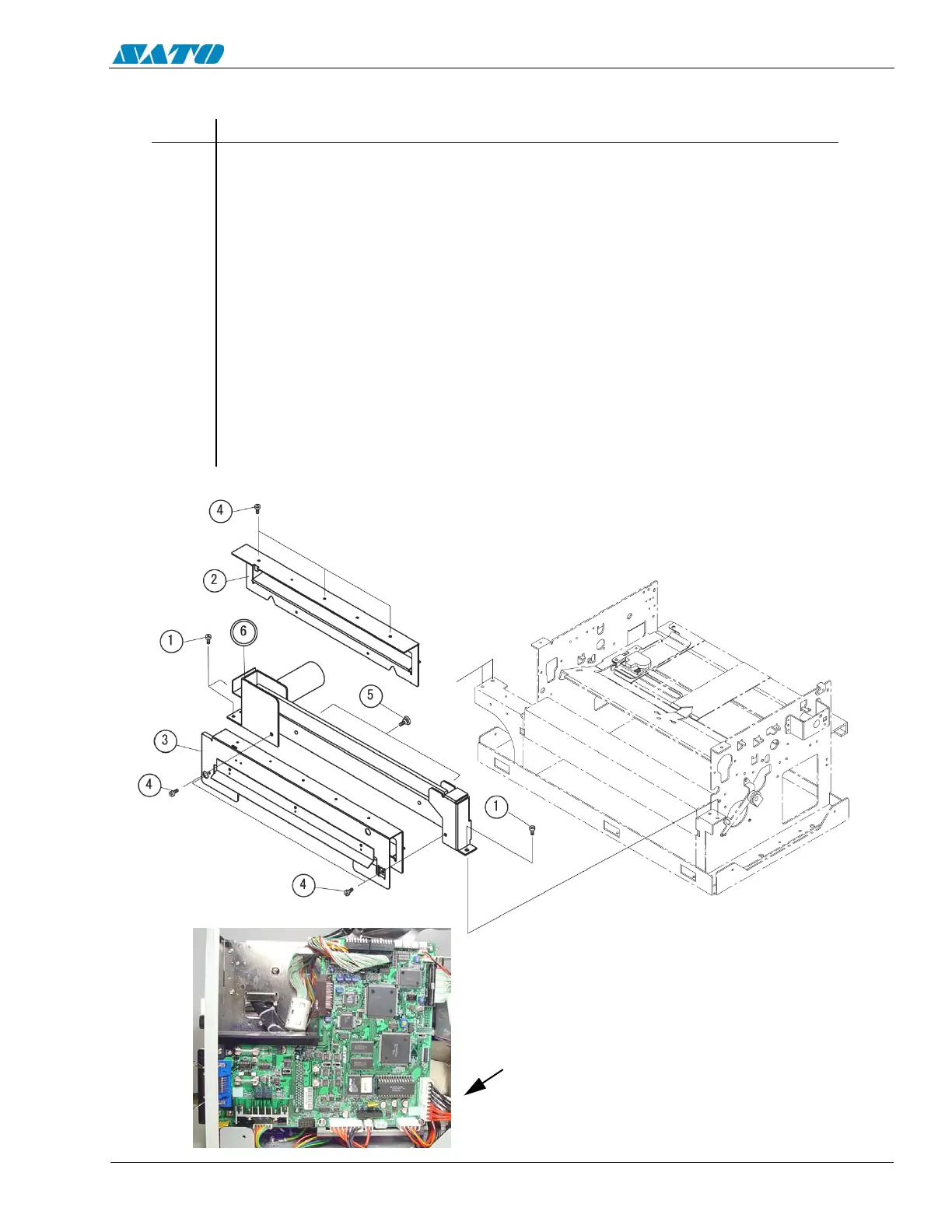
STEP PROCEDURE
1. Switch the printer OFF and disconnect the power cord.
2. Refer to Section 6.2 and remove the covers.
3. Detach the CUTSEN/CUTTER connector from the main circuit board.
4. Remove (3) Item 1 screws from Item 6 Cutter Unit.
5. Remove (3) Item 4 screws from Item 2 Cutter Bracket.
6. Remove (4) Item 4 screws from Item 3 Cutter Bracket
7. Remove (2) Item 5 Guide screws from Item 6 Cutter Unit
8. Remove and replace the Cutter Unit.
9. Reattach the cable CUTSEN/CUTTER connection to the main circuit board.
10. Replace the covers.
6.18 Replacing the Cutter Unit
DETACH THE CUTSEN/
CUTTER CONNECTOR
ON THE MAIN CIRCUIT
BOARD

Table of Contents

Other manuals for SATO E series

Questions and Answers:

Question and Answer IconNeed help?

Do you have a question about the SATO E series and is the answer not in the manual?

SATO E series Specifications

General IconGeneral
Print MethodThermal Transfer / Direct Thermal
Max. Print Speed6 ips (inches per second)
Max. Print Width4.09 inches (104 mm)
InterfacesUSB, Ethernet
Media TypeLabels, Tags, Ticket
Ribbon LengthUp to 984 ft (300 m)
Power SupplyAC 100-240V, 50/60 Hz
Print Resolution203 dpi

Related product manuals