SATO M-10e TT/DT Printers Service Manual
PN 900109
Rev. A
6-22
Section 6. Replacement Procedures
STEP PROCEDURE
1. Switch the printer OFF and disconnect the power cord.
2. Refer to Section 6.9 and remove the Interface PCB if installed.
3. Refer to Section 6.2 and remove the covers.
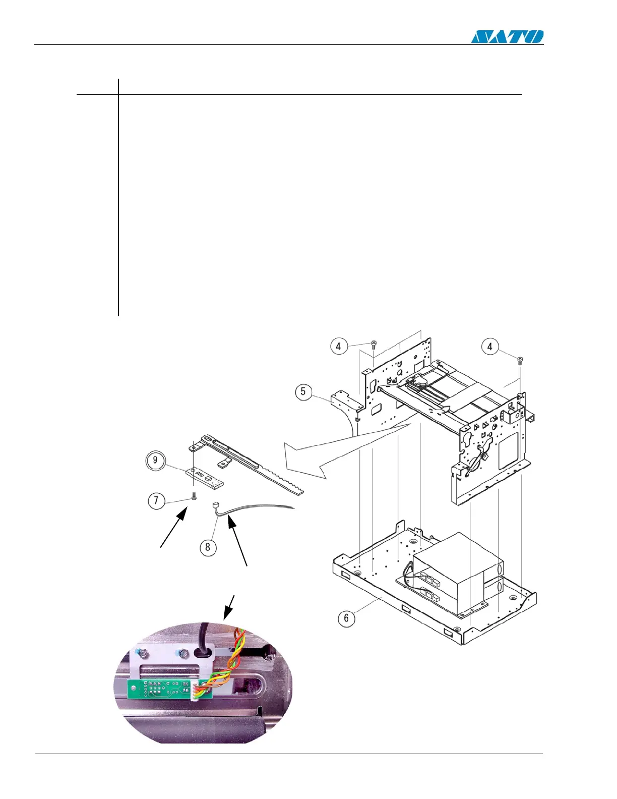
4. Remove (7) Item 4 screws to detach the main chassis from the base.
5. Detach (1) Item 8 connector from Item 9 SEN1 PCB.
6. Remove (1) Item 7 screw to detach SEN1 PCB from the plate rack.
7. Remove and replace SEN1 PCB.
8. Reattach the base to the main chassis.
9. Replace the covers.
10. Refer to Section 4.5 “Adjustment of Eyemark Sensor”.
6.15b Replacing the Pitch Sensor (SEN1 PCB ) (Eye-Mark Sensor)
DETACH THE MAIN
CHASSIS FROM THE BASE
REMOVE ITEM 7
SCREW TO DETACH
FROM ITEM 9
SEN1 PCB
DETACH ITEM 8
CONNECTOR

 Loading...


