EasyManuals Logo

SATO E series Service Manual

SATO E series
206 pages
To Next Page IconTo Next Page
To Previous Page IconTo Previous Page
Page #82 background imageLoading...
Page #82 background image
SATO M-10e TT/DT Printers Service Manual
PN 900109
Rev. A
4-4
Section 4. Electrial Checks and Adjustments
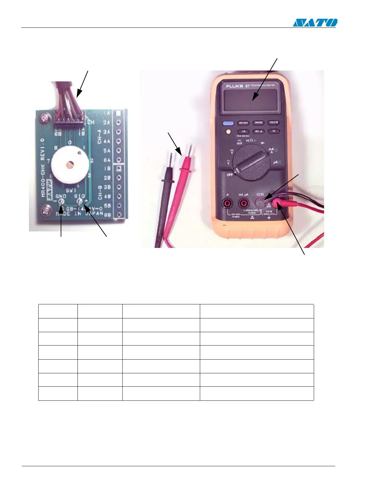
DC Power Voltage Checks
SIG PIN
CABLE TO PCB
TP TEST MODULE
LCD DISPLAY
GROUND
PIN
DIGITAL
MULTIMETER
VOLT
PROBES
COM
TEST POINT CHART
NOTE: The power supply voltages are not adjustable. All voltages must read
within +/- 10% of the nominal value for correct operation of the printer.
Dial POS DISC VOLTAGE RANGE TP TEST MODULE
SG
NC
0 +5V +4.8V to +5.2V CHA3 (+5.0V) - CHA1 (GND)
1 +2V +1.9V to +2.1V CHA4 (+2.0V) - CHA1 (GND)
2 +3.3V +3.1V to +3.5V CHA5 (+3.3V) - CHA1 (GND)
3 +24V +23.5V to 24.5V CHA6 (+24.0V) - CHA1 (GND)

Table of Contents

Other manuals for SATO E series

Questions and Answers:

Question and Answer IconNeed help?

Do you have a question about the SATO E series and is the answer not in the manual?

SATO E series Specifications

General IconGeneral
Print MethodThermal Transfer / Direct Thermal
Max. Print Speed6 ips (inches per second)
Max. Print Width4.09 inches (104 mm)
InterfacesUSB, Ethernet
Media TypeLabels, Tags, Ticket
Ribbon LengthUp to 984 ft (300 m)
Power SupplyAC 100-240V, 50/60 Hz
Print Resolution203 dpi

Related product manuals