PN 9001098
Rev. A
4-3
SATO M-10e TT/DT Printers Service Manual
Section 4. Electrical Checks and Adjustments
STEP PROCEDURE
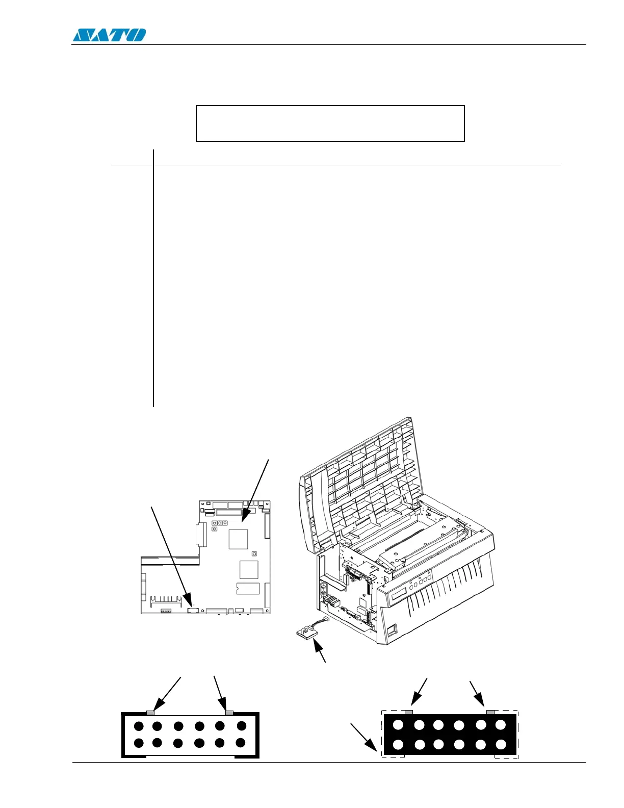
1. Refer to illustrations and charts on pages 4-3, 4-4 and 4-5. Attach the connector
from the TP Test Module to the test port on the main circuit board. Note the correct
positioning of the connector. Nibs on the connector are placed down in the
receptacle on the main circuit board in the forward position.
2. Attach the ground wire of the multimeter to the TP Test Module Gnd pin.
3. Attach the positive wire of the multimeter to the +SIG pin on the TP Test Module
terminal.
4. Turn the printer on and rotate the dial to a dial POS on the TP Test Module. Record
the values from the Multimeter LCD.
5. Confirm voltages are correct. If not, then replace the power supply. Refer to
Section 6.10.
6. After performing the tests, switch off the power and replace the left side cover.
4.3 DC Power Voltage Checks
To check voltage levels, first check the fuses (Section 6.12) and replace if necessary. Refer to
Section 4.2 and remove the left side cover and perform the following steps.
Additional equipment required: TP Test Module
Digital Multimeter
TP TEST
MODULE TO
PCB TEST
POINT
CORRECT
POSITION OF NIBS
ON CONNECTOR
CONNECTOR
RECEPTACLE ON
MAIN CIRCUIT
BOARD
CORRECT
POSITION OF NIBS
ON CONNECTOR
MAIN CIRCUIT
BOARD

 Loading...


