EasyManuals Logo

SATO E series Service Manual

SATO E series
206 pages
To Next Page IconTo Next Page
To Previous Page IconTo Previous Page
Page #80 background imageLoading...
Page #80 background image
SATO M-10e TT/DT Printers Service Manual
PN 900109
Rev. A
4-2
Section 4. Electrial Checks and Adjustments
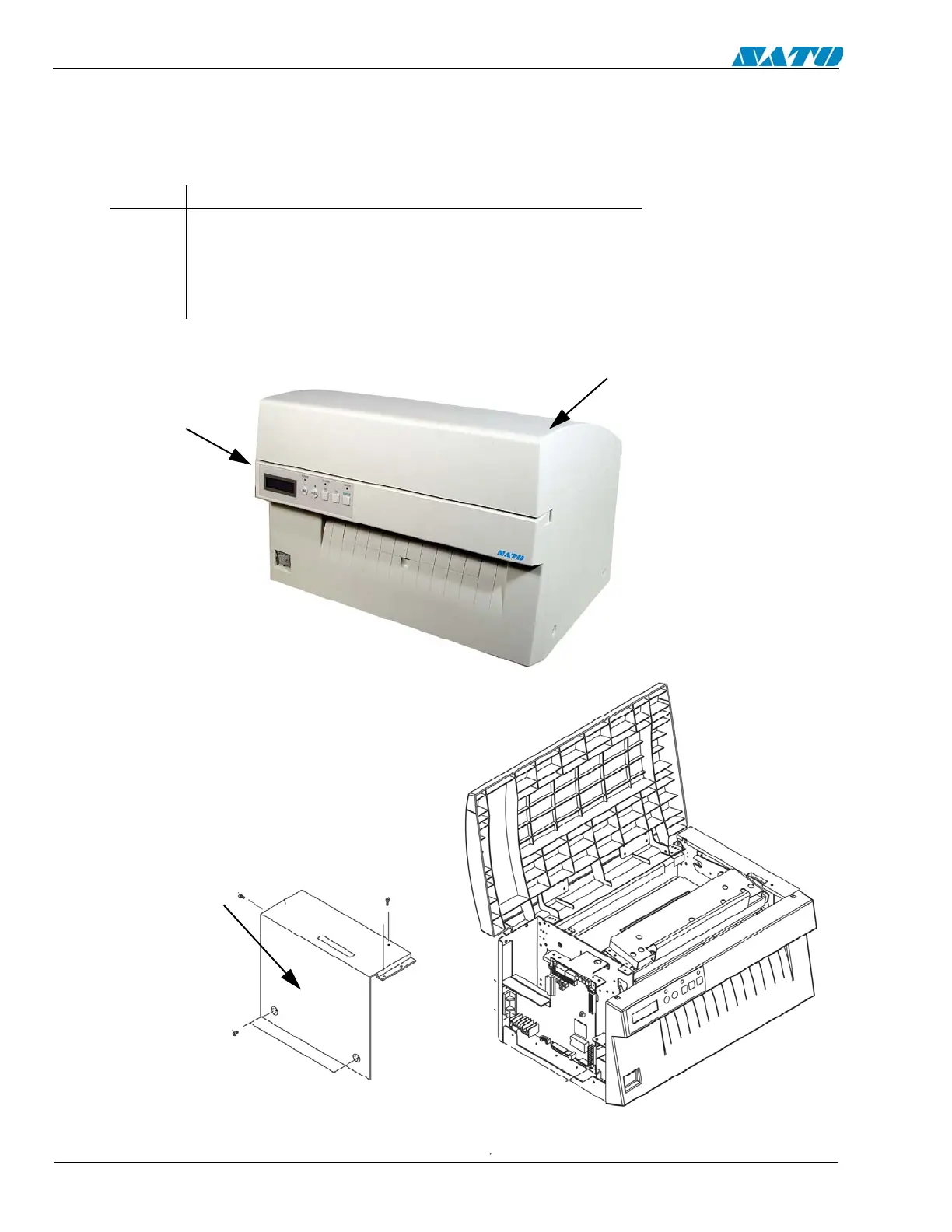
4.2 Steps Prior to Some Procedures
Some procedures in this section require access to potentiometers and the test point
connector located on the main circuit board. Raise the Access Cover and detach the left
side cover for accessing the main circuit board.
STEP PROCEDURE
1. Switch the printer OFF and disconnect the power cord.
2. Raise and remove the Access Cover.
3. Unfasten (5) screws from the left side cover and remove.
ACCESS COVER
LEFT SIDE
COVER
LEFT SIDE
COVER

Table of Contents

Other manuals for SATO E series

Questions and Answers:

Question and Answer IconNeed help?

Do you have a question about the SATO E series and is the answer not in the manual?

SATO E series Specifications

General IconGeneral
Print MethodThermal Transfer / Direct Thermal
Max. Print Speed6 ips (inches per second)
Max. Print Width4.09 inches (104 mm)
InterfacesUSB, Ethernet
Media TypeLabels, Tags, Ticket
Ribbon LengthUp to 984 ft (300 m)
Power SupplyAC 100-240V, 50/60 Hz
Print Resolution203 dpi

Related product manuals