SATO M-10e TT/DT Printers Service Manual
PN 900109
Rev. A
6-12
Section 6. Replacement Procedures
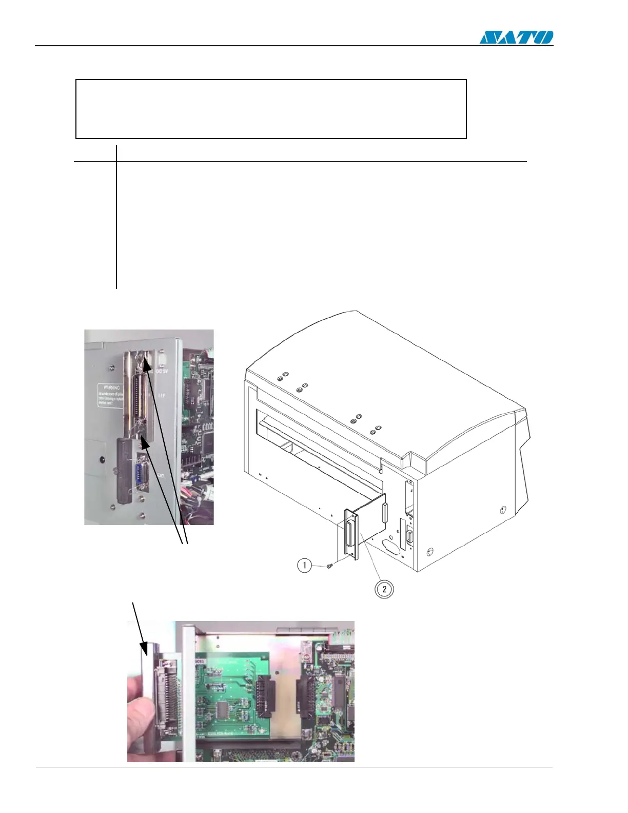
6.9 Replacing the Interface PCB
NOTE: Many of the components on this board are susceptible to damage by
static electricity. To avoid damage from static discharges, do not unpack
new circuit boards from anti-static bags until instructed to do so, and use a
wrist grounding strap.
STEP PROCEDURE
1. Switch the printer OFF and disconnect the power cord.
2. Remove (2) Item 1 screws holding Item 2 Interface PCB from the back side of the
unit. Pull away to detach the connector on the interface from the main circuit
board.
3. Replace/substitute optional Interface PCB.
4. Complete the Factory Reset Procedure.
REMOVE (2)
SCREWS AND PULL
AWAY TO DETACH
INTERFACE PCB

 Loading...


