EasyManuals Logo

SATO E series Service Manual

SATO E series
206 pages
To Next Page IconTo Next Page
To Previous Page IconTo Previous Page
Page #123 background imageLoading...
Page #123 background image
PN 9001098
Rev. A
6-19
SATO M-10e TT/DT Printers Service Manual
Section 6. Replacement Procedures
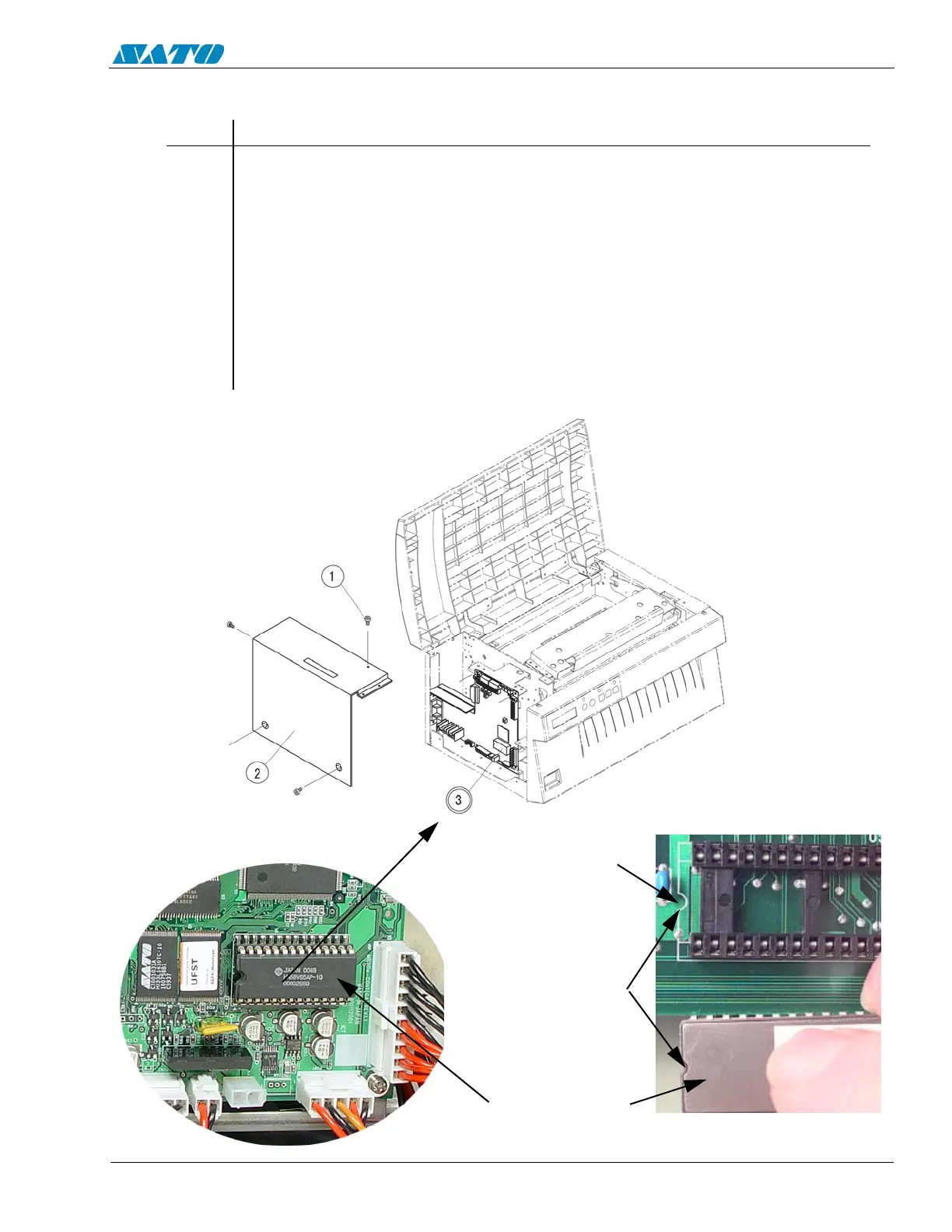
6.13 Replacing the EEPROM
STEP PROCEDURE
1. Switch the printer OFF and disconnect the power cord.
2. Unfasten (5) screws from the left side cover and remove.
3. Remove the Item 3 EEPROM chip at location shown in illustration below.
4. Install the new EEPROM chip being careful to properly align the chip, using the
“U” shaped notch as a reference. Be careful not to bend any of the EEPROM legs
and that it is set securely in the socket.
5. Replace the left side cover.
6. Complete the Factory Reset Procedure.
NOTCH OUTLINE
ON BOARD
ALIGN NOTCHES
EEPROM CHIP

Table of Contents

Other manuals for SATO E series

Questions and Answers:

Question and Answer IconNeed help?

Do you have a question about the SATO E series and is the answer not in the manual?

SATO E series Specifications

General IconGeneral
Print MethodThermal Transfer / Direct Thermal
Max. Print Speed6 ips (inches per second)
Max. Print Width4.09 inches (104 mm)
InterfacesUSB, Ethernet
Media TypeLabels, Tags, Ticket
Ribbon LengthUp to 984 ft (300 m)
Power SupplyAC 100-240V, 50/60 Hz
Print Resolution203 dpi

Related product manuals