SATO M-10e TT/DT Printers Service Manual
PN 900109
Rev. A
6-10
Section 6. Replacement Procedures
The Main Circuit Board contains the control electronics for the printer and is located
behind the left side cover. The I/O PCB interface and optional memory card unit if
installed, which are attached to the main circuit board, must first be removed.
6.8 Replacing the Main Circuit Board
NOTE: Many of the components on this board are susceptible to damage by
static electricity. To avoid damage from static discharges, do not unpack
new circuit boards from anti-static bags until instructed to do so, and use a
wrist grounding strap.
STEP PROCEDURE
1. Switch the printer OFF and disconnect the power cord.
2. Refer to illustrations on pages 6-10 and 6-11.
Unfasten (5) screws from the left side cover and remove.
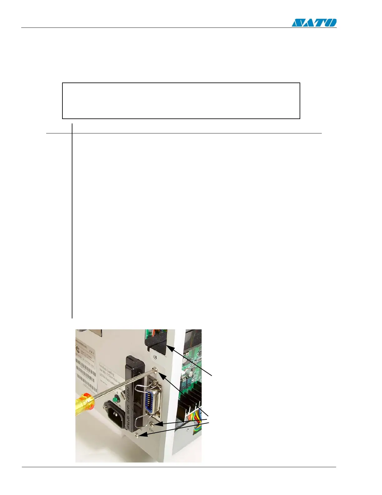
3. Remove (2) screws holding the I/O PCB interface from the back side of the unit.
Pull away to detach the connector on the interface from the main circuit board.
Refer to Section 6.9.
4. Remove (3) screws with washers from the back panel, (2) at EXT connector and
(1) under “SLOT”.
5. Note cable connection locations, then carefully disconnect the cables from the
main circuit board.
6. Remove (4) screws with washers from the PCB board to the bracket. Remove and
replace the board.
7. Replace the left side cover.
8. Complete the Factory Reset Procedure.
REMOVE (3) SCREWS, TWO
AT “EXT” CONNECTOR AND
ONE UNDER “SLOT”
INTERFACE CARD SHOWN
REMOVED. REFER TO
SECTION 6.9

 Loading...


