EasyManuals Logo

SATO E series Service Manual

SATO E series
206 pages
To Next Page IconTo Next Page
To Previous Page IconTo Previous Page
Page #83 background imageLoading...
Page #83 background image
PN 9001098
Rev. A
4-5
SATO M-10e TT/DT Printers Service Manual
Section 4. Electrical Checks and Adjustments
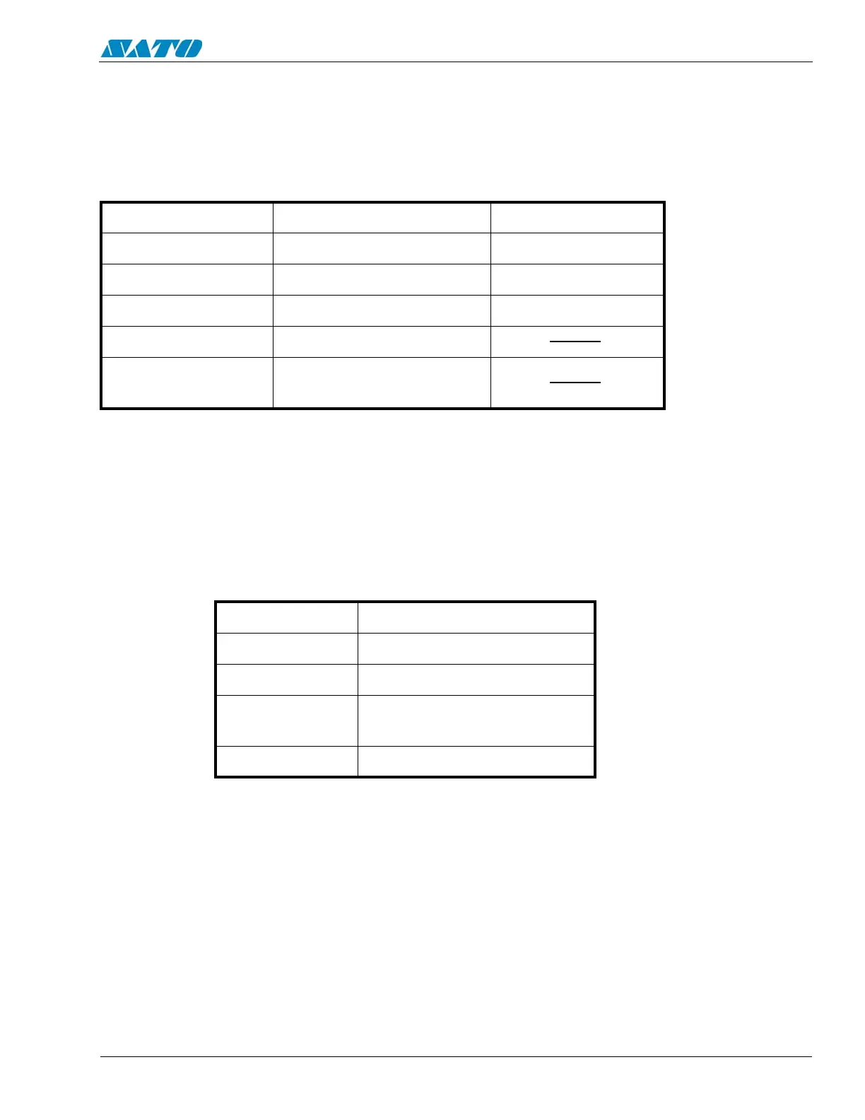
4.4 Potentiometer Assignments
POTENTIOMETERS ARE
LOCATED ON MAIN
CIRCUIT BOARD
POTENTIOMETERS ARE LOCATED
UNDERNEATH A FLIP COVER ON THE
FRONT PANEL
VR TO ADJUST ITEM POSITION DIAL
VR5 (IM) Eye Mark Sensor 4
VR6 (GAP) Gap Sensor 5
VR7 (PS) Label Penetrating Sensor 8
VR8 (PE) Paper End Sensor
VR9 (PITCH) Pitch
(Use with VR3 on Cover)
VR TO ADJUST ITEM
VR1 Print Darkness
VR2 Offset
VR3 Pitch Correction
(Use with VR9 on Main PCB)
VR4 Display

Table of Contents

Other manuals for SATO E series

Questions and Answers:

Question and Answer IconNeed help?

Do you have a question about the SATO E series and is the answer not in the manual?

SATO E series Specifications

General IconGeneral
Print MethodThermal Transfer / Direct Thermal
Max. Print Speed6 ips (inches per second)
Max. Print Width4.09 inches (104 mm)
InterfacesUSB, Ethernet
Media TypeLabels, Tags, Ticket
Ribbon LengthUp to 984 ft (300 m)
Power SupplyAC 100-240V, 50/60 Hz
Print Resolution203 dpi

Related product manuals