Table of Contents
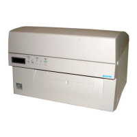
SATO M-10e TT/DT Printers Service Manual
PN 9001098
Rev. A
ii
Section 5. Mechanical Adjustments Page
1 Overview ........................................................................................... 5-1
2 Timing Belt Adjustment ..................................................................... 5-2
3 Head Facing Adjustment (Print Balance) .......................................... 5-3
4 Print Head Front and Rear Alignment (Print Balance) ...................... 5-4
5 Ribbon Tension Adjustment (Part 1 ................................................... 5-5
Ribbon Tension Adjustment (Part 2) .................................................. 5-6
Section 6. Replacement Procedures ........................................................
1 Overview ............................................................................................ 6-1
2 Steps Prior to Some Procedures....................................................... 6-2
3 Replacing the Print Head TT/DT ....................................................... 6-4
4 Replacing the Timing Belt ................................................................. 6-6
5 Replacing the Platen Roller............................................................... 6-7
6 Replacing the Feed Roller................................................................. 6-8
7 Replacing the LC/Keyboard PCB ...................................................... 6-9
8 Replacing the Main Circuit Board...................................................... 6-10
9 Replacing the Interface PCB ............................................................. 6-12
10 Replacing the Power Supply ........................................................... 6-13
11 Replacing the Stepper Motor........................................................... 6-15
12 Replacing the Fuse(s) ..................................................................... 6-17
13 Replacing the EEPROM.................................................................. 6-19
14 Replacing the Ribbon PCB.............................................................. 6-20
15a Replacing the Pitch Sensor (SEN2 PCB) (Gap Sensor) ............... 6-21
15b Replacing the Pitch Sensor (SEN1 PCB) (Eye-Mark Sensor)....... 6-22
16 Replacing the Label Penetrating Sensor (SEN3 PCB).................... 6-23
17 Replacing the Ribbon Sensor (CSEN PCB) TT Unit ....................... 6-24
18 Replacing the Cutter Unit ................................................................ 6-25
Section 7. Factory Resets
1 Overview ............................................................................................ 7-1
2 Factory Settings/Test Print ................................................................ 7-2
3 Clear Head Counters......................................................................... 7-3
4 Clear Cutter Counters ....................................................................... 7-4
5 Clear EEPROM .................................................................................. 7-5
6 Sample Test Prints ............................................................................ 7-6
Section 8. Troubleshooting
1 Overview ............................................................................................ 8-1
2 Check List.......................................................................................... 8-2
3 The IEEE 1284 Parallel Interface ...................................................... 8-4
4 The RS232C Serial Interface ............................................................ 8-5
5 The Universal Serial BUS (USB)....................................................... 8-6
6 The Lan Ethernet Interface................................................................ 8-6
7 Error Signals...................................................................................... 8-12
8 Error Screens .................................................................................... 8-13
9 Troubleshooting Tables..................................................................... 8-17
10 Head Pattern Examples .................................................................. 8-20
11 Hex Dump Diagnostic Labels .......................................................... 8-22

 Loading...