SATO M-10e TT/DT Printers Service Manual
PN 9001098
Rev. A
3-6
Section 3. Interface Specifications
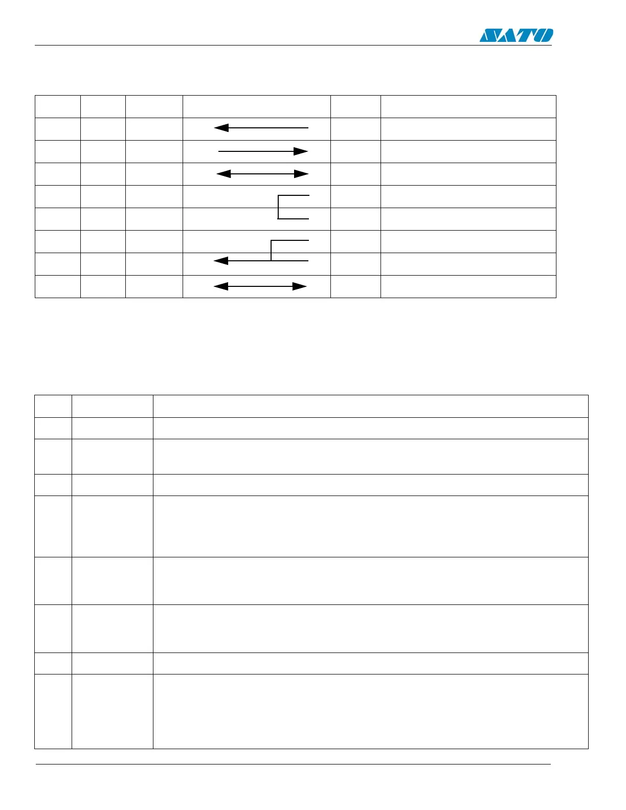
DB9 DB25 HOST INTERCONNECTION DB25 PRINTER
1 1 FG 1 FG (Frame Ground)
2 3 RD 2 TD (Transmit Data)
3 2 TD 3 RD (Receive Data)
8 5 CTS 4 RTS (Request to Send)
7 4 RTS 5 CTS (Clear to Send)
4 20 DTR 6 DSR (Data Set Ready)
6 6 DSR* 20 DTR (Data Terminal Ready)
5 7 SG 7 SG (Frame Ground)
* This connection at the host side of the interface would depend upon the pin that is being used as the Ready/
Busy signal by the driving software. Typically on a PC, it would be either CTS (pin 5) or DSR (pin 6) on a
DB-25 connector.
NOTE: SATO does not recommend the use of mechanical data switches commonly called A/B switches, as
they are known to damage both the computer and printer parallel ports.
RS232C Serial Interface
Cable Requirements
PIN DIRECTION SIGNAL DESCRIPTION
1 Reference FG (Frame Ground)
2 To Host TD (Transmit Data) - Data from the printer to the host computer.
Sends X-On/X-Off characters or status data (Bi-Directional protocol)
3 To Printer RD (Receive Data) - Data to the printer from the host computer
4 To Host RTS (Request to Send) - Used with Ready/Busy flow control to indicate an error con-
dition. RTS is high and remains high unless the print head is open (in this case, RTS
would return to the high state after the print head is closed and the printer is placed
back on-line) or an error condition occurs during printing (e.g. label out)
5 To Printer CTS (Clear to Send) - When this line is high, the printer assumes that data is ready to
be transmitted. The printer will not receive data when this line is low. If this line is not
being used, it should be tied high (to pin 4).
6 To Printer DSR (Data Set Ready) - When this line is high, the printer will be ready to receive
data. This line must be high before data is transmitted. If this line is not being used, it
should be tied high (to pin 20).
7 Reference SG (Signal Ground)
20 To Host DTR (Data Terminal Ready - This signal applies to Ready/Busy flow control. (The
printer is ready to receive data when this pin is high. It goes low when the printer is
off-line either manually or due to an error condition and while printing in the Single
Job Buffer mode. It will also go low when the data in the buffer reaches the Buffer
Near Full level.

 Loading...


