8015416/ZPN2/2017-09-08 • © SICK AG • Subject to change without notice 31
Operating instructions Distance measuring device DL100 – CANopen®
Mounting
6.5 Place the distance measuring device towards the adjacent data trans-
mission photoelectric switch
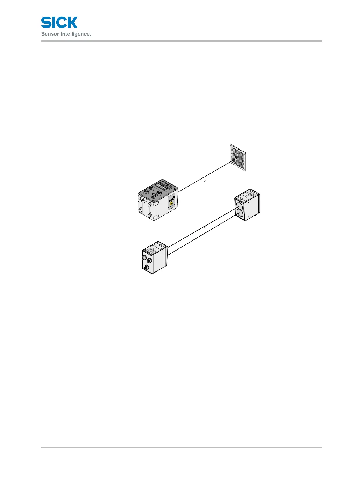
When mounting with a data transmission photoelectric switch of the
ISD300, ISD400-1xxx and ISD400-6xxx series, a beam separation of at
least 100 mm must be complied with at all times. The maximum scan-
ningrangedoesnotinuencetheminimumdistance.Fordevicesofthe
ISD400-7xxx (ISD400 Pro) serie other minimum distances apply. Refer to
operating instructions “ISD400 Pro”.
Formula a≥100mm
a
Fig. 11: Placement of the distance measuring device to the data transmission
photoelectric switch ISD
1 Distance measuring device DL100
2 Reector
3 Data transmission photoelectric switch ISD300, ISD400-1xxx or ISD400-6xxx
a Minimum distance