8015416/ZPN2/2017-09-08 • © SICK AG • Subject to change without notice 39
Operating instructions Distance measuring device DL100 – CANopen®
Electrical connection
Fig. 20: Briey connect shield with a large area - earth both sides
7.3 Electrically connect distance measuring device
NOTE!
The distance measuring device has the connection
diagram and information on the inputs and outputs on
the type sign.
You can connect the supply voltage either separately via
connection 1 or in combination with the CANopen com-
munication via connection 3 or connection 4.
1. Ensure that there is no voltage applied.
2. Connect the measuring device according to the connection diagram.
12
34
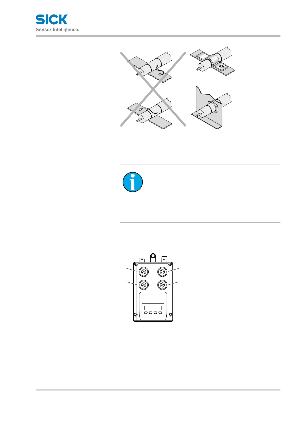
Fig. 21: Position of the electrical connections
1 Plug 1: Supply voltage (Pwr)
2 Socket 2: Ethernet
3 Socket 3: CANopen
®
output
4 Plug 4: CANopen
®
input