8015416/ZPN2/2017-09-08 • © SICK AG • Subject to change without notice 23
Operating instructions Distance measuring device DL100 – CANopen®
Setup and function
4.3 Display and operating elements
EscSet
PWR
MF1
MF2
LNK
STA
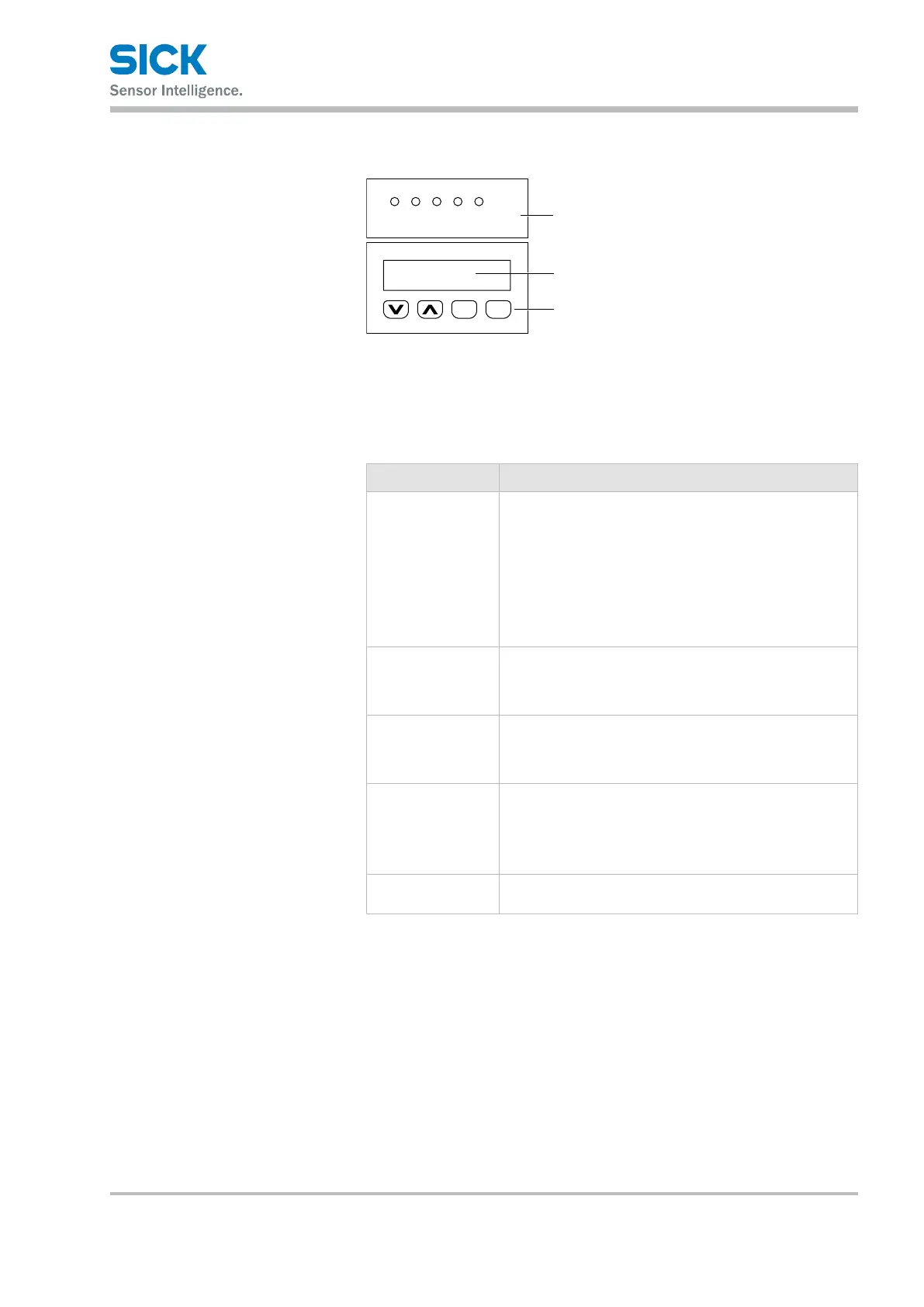
Fig. 5: Display and operating elements
1 LEDs
2 Display
3 Keys
LEDs
LED Description
PWR Display of operating status
• LEDo:Nooperation
• LED green: Trouble-free operation
• LEDorangeashing:Warning(seewarningstatus,upper
level menu)
• LEDredashing:Interference(seeerrorstatus,menu
on the top level)
→ Troubleshooting, see page 121, chapter 12.
MF1 The status for multi-function input/output MF1.
• LED on: Output high
• LEDo:Outputlow
MF2 The status for multifunction output MF2.
• LED on: Output high
• LEDo:Outputlow
LNK Ethernet
• LEDo:NoEthernetpresent
• LED green: Ethernet present
• LEDorangeashing:Datatransmission
STA Interface CANopen
®
→ Status LED, page 119, Table 72.
Table 1: LEDs