Operating instructions Distance measuring device DL100 – CANopen®
Mounting
28 © SICK AG • Subject to change without notice • 8015416/ZPN2/2017-09-08
6.3 Chooseandmountreector
NOTE!
→ For suitable reectors and suitable reective tape, see
page 130, chapter 15.1
Reectorsize • Selectthereectorsizesothatthelightspotdoesstillmeetthereector
in case of vibrations.
• Ifthereectorisinstalledatavehicle,asmallerreectoristypicallysuf-
cient.
Requirements • Highlyreectivesurfacesclosetothereectorcancausebeamdeec-
tions or stray light and thus lead to incorrect measurements. Highly re-
ectivesurfacesmaybe,amongothers,shelfproles,paletteswrapped
with stretch foil and running rails.
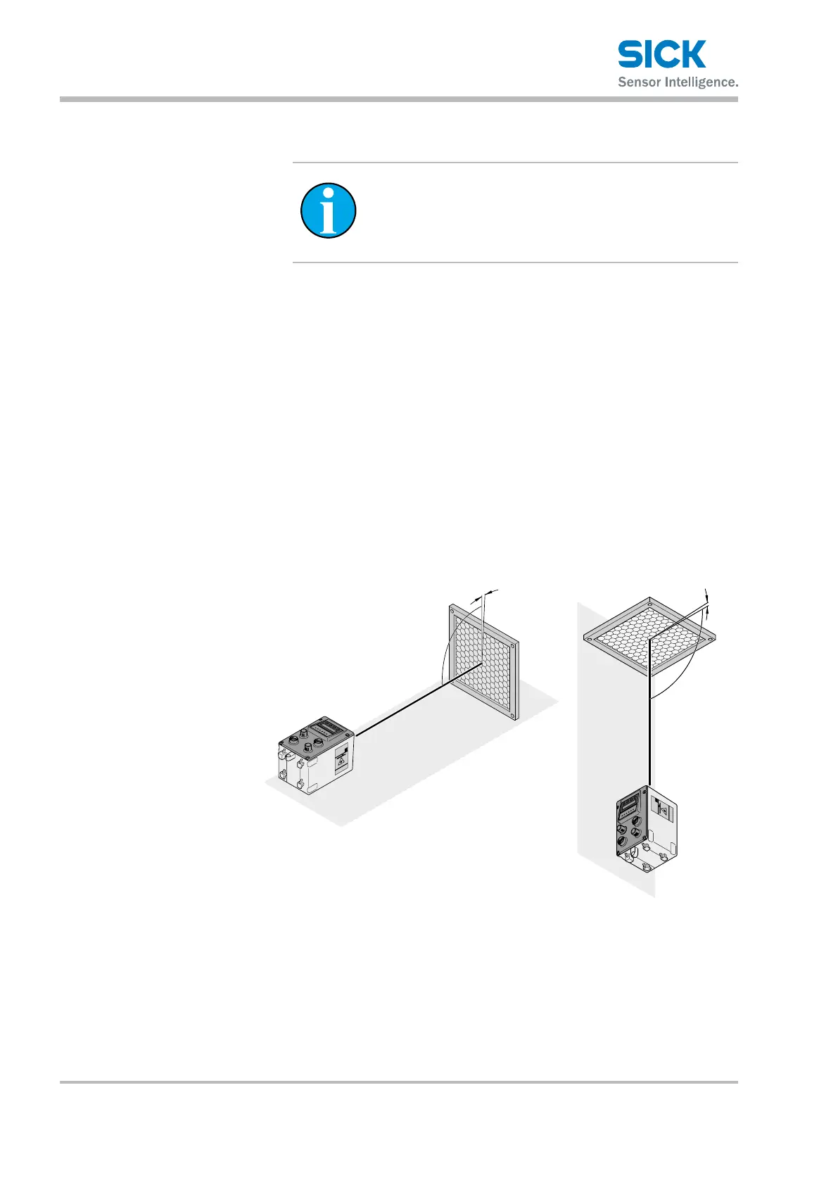
• When mounting the distance measuring device in the horizontal axis of
stackercrane,inclinethereectortowardstheceiling,awayfromtherail
(approx. 1°to 3°). →Seefollowinggure.
• When mounting in the vertical axis, incline away from the stacker
crane‘s mast (approx. 1°to 3°). →Seefollowinggure.
S
et
E
s
c
<
<
S
e
t
E
s
c
<
<
Fig. 8: Installing the reector on highly reective surfaces
Left: Installed in driving axis, installed at the right in the lifting axis
1 Distance measuring device
2 Highly reective surface
3 Reector
4 Inclination of approx. 1° to 3°