Operating instructions Distance measuring device DL100 – CANopen®
Electrical connection
40 © SICK AG • Subject to change without notice • 8015416/ZPN2/2017-09-08
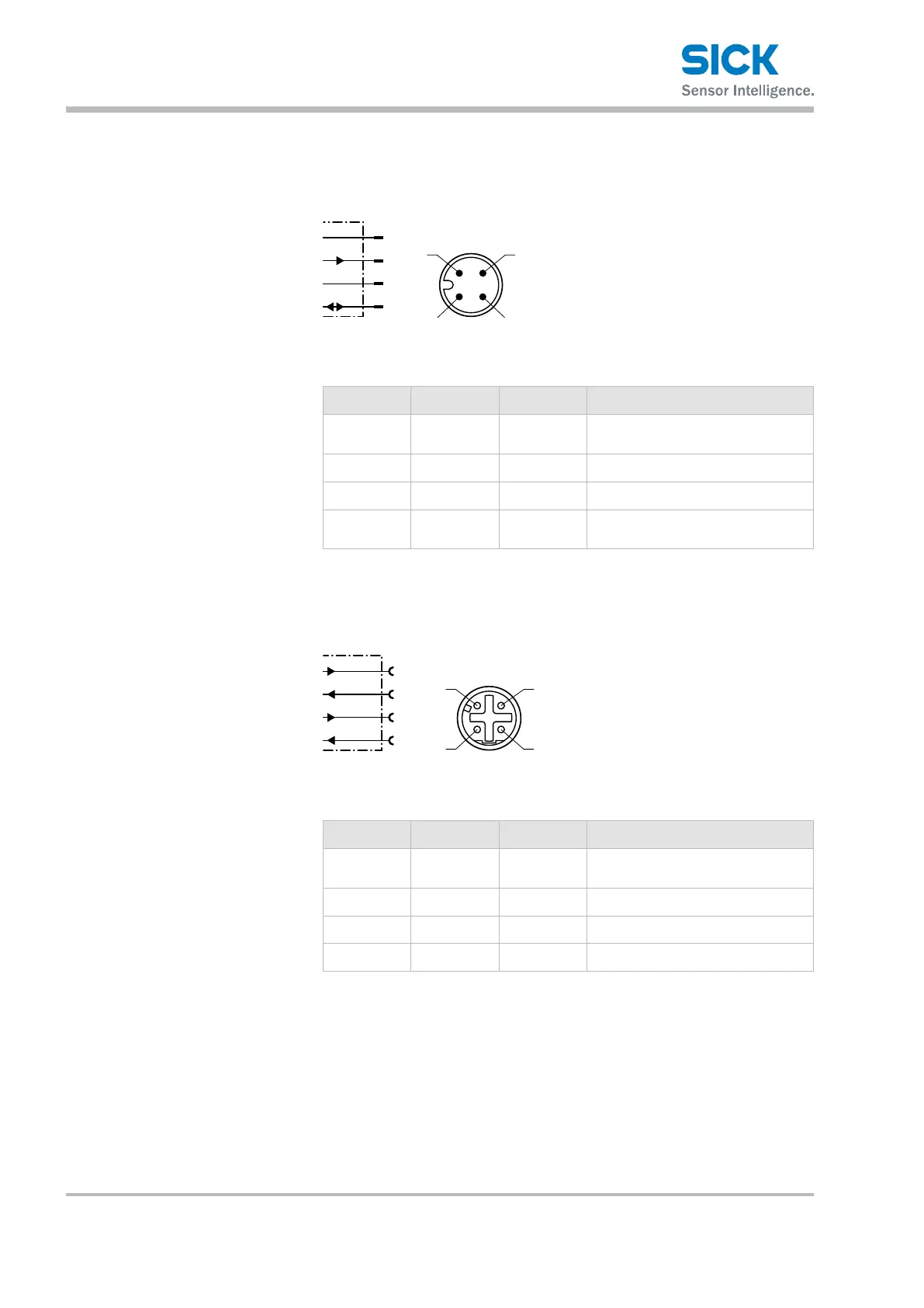
7.4 Connection diagrams
7.4.1 Connection diagram supply voltage
L+
M
MF
1
2
4
wht
blu
brn
blk
3
Fig. 22: Connection diagram supply voltage,
plug M12, 4-pin, A-coded
Contact Marking Wire color Description
1 L+ brown Supply voltage:
+18…+30VDC
2 MF2 white Multifunction output MF2 type B
3 M blue Supply voltage: 0 V
4 MF1 black Multifunctional input and
output MF1 type B
Table 5: Description plug supply voltage
7.4.2 Connection diagram Ethernet
Tx+
Tx–
Rx
1
2
4
wht/grn
ora
wht/ora
grn
3
Fig. 23: Connection diagram Ethernet,
socket M12, 4-pin, D-coded
Contact Marking Wire color Description
1 Tx+ white/or-
ange
Send data signal, not inverted
2 Rx+ white/green Receive data signal, not inverted
3 Tx– orange Send data signal, inverted
4 Rx– green Receive data signal, inverted
Table 6: Description socket Ethernet