8015416/ZPN2/2017-09-08 • © SICK AG • Subject to change without notice 41
Operating instructions Distance measuring device DL100 – CANopen®
Electrical connection
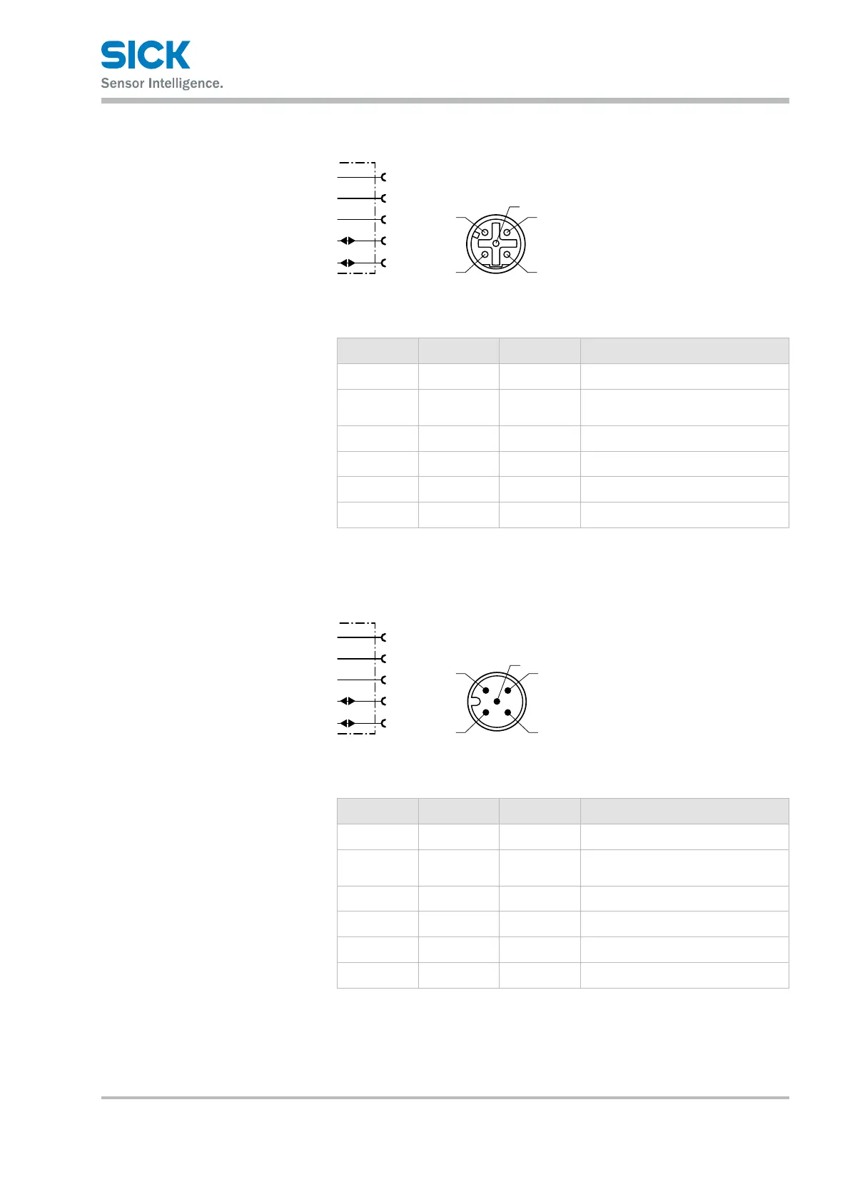
7.4.3 Connection diagram CANopen
®
output
FE
V+
CAN_H
1
2
4
red
blk
wht
blu
V–
3
CAN_L
5
4
Fig. 24: Connection diagram CANopen
®
output
socket M12, 5-pin, A-coded
Contact Marking Wire color Description
1 FE Shield Cable shield
2 V+ red Supply voltage:
+10…+30VDC
3 V– black Supply voltage: 0 V
4 CAN_H white CAN bus signal
5 CAN_L blue CAN bus signal
Thread FE Shield Cable shield (housing)
Table 7: Description socket CANopen
®
output
7.4.4 Connection diagram CANopen
®
input
FE
V+
CAN_H
1
2
4
red
blk
wht
blu
V–
3
CAN_L
5
2
Fig. 25: Connection diagram CANopen
®
input,
plug M12, 5-pin, A-coded
Contact Marking Wire color Description
1 FE Shield Cable shield
2 V+ red Supply voltage:
+10…+30VDC
3 V– black Supply voltage: 0 V
4 CAN_H white CAN bus signal
5 CAN_L blue CAN bus signal
Thread FE Shield Cable shield (housing)
Table 8: Description plug CANopen
®
input