Monitoring case switching using two static input pairs
S300 Professional
1
5
19
7
10
22
13
15
3
FE
6
16
20
8
9
21
14
4
2
S1
k1
k2
A1 A2 B2 B1
K1 K2 H3 H8 H2
+24 V
FE
0 V
k2k1
x
x
y
y
z
z
k2
k1
1)
E113153/01/2015-03-25
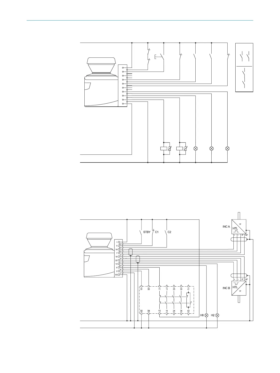
Figure 41: Connection diagram for monitoring case switching using two static input pairs
S300 Pr
ofessional in conjunction with relays (contactors); Operating mode: with restart
interlock and external device monitoring; Monitoring case switching by the control
inputs A and B.
Monitoring case switching using static and dynamic inputs
S300 Professional
+24 V
FE
0 V
UE10-3OS
Figure 42: Connection diagram for monitoring case switching using static and dynamic inputs
PROJECT PLANNING 4
8010948/ZA21/2020-06-18 | SICK O P E R A T I N G I N S T R U C T I O N S | S300
53
Subject to change without notice

 Loading...


