In those places where the surrounding contour is larger than the protective field range
3, t
he protective field corresponds to the possible scanning range.
WARNING
P
ersons or parts of the body to be protected may not be recognized or not recognized in
time in case of non-observance.
The protective field suggested by the CDS is not a replacement for the calculation of the
minimum distance, see "Mounting", page 58.
Before commissioning the machine or vehicle, check the configuration of the protective
fields, see "Commissioning", page 103, see "Checklist for initial commissioning and
commissioning", page 148.
b
Calculate the minimum distance.
b
Check the configured protective fields.
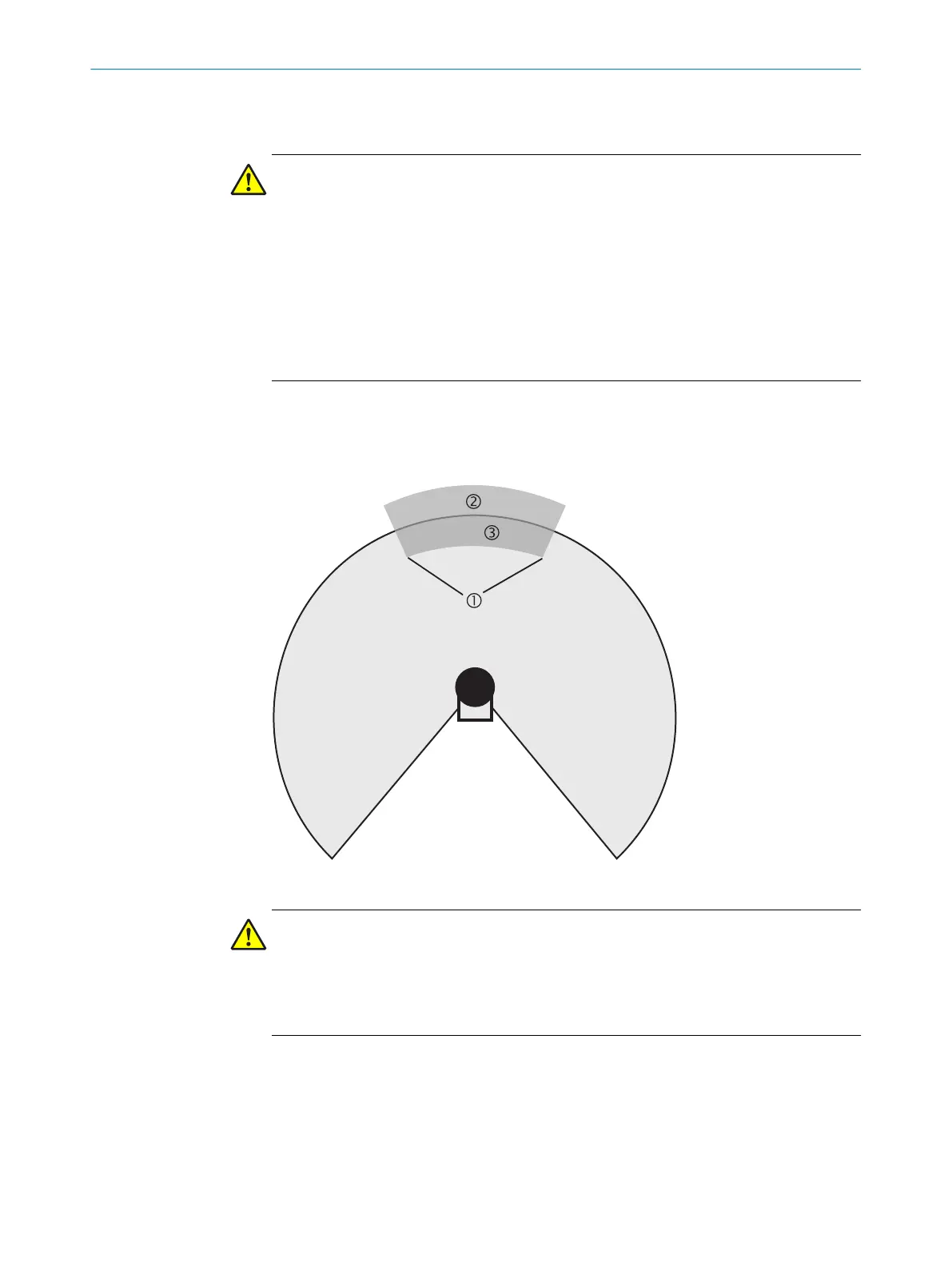
7.12.4 Using the contour as a reference
In addition to the protective field, the device can also monitor a contour (e.g., the floor
in v
ertical applications).
Figure 66: Schematic diagram of contour as reference
WARNING
D
angerous state of the machine
If a contour segment is smaller than the configured resolution, a change in the contour
or a change in the position of the device may not be detected.
b
Define contour segments that are larger than the configured resolution.
For contour monitoring you define a contour segment 1. The contour segment com‐
prises a positive 2 and a negative 3 tolerance band.
The OSSDs of the device swiched to the OFF state in the following situations:
•
There is an object in the protective field.
•
The monitored surrounding contour is no longer in the tolerance band, e.g., if a
door is opened or the position of the safety laser scanner is changed.
7 C
ONFIGURATION
92
O P E R A T I N G I N S T R U C T I O N S | S300 8010948/ZA21/2020-06-18 | SICK
Subject to change without notice

 Loading...


