7.7.1 Pulses per cm travel that are output by the incremental encoders
Overview
T
he result depends on the number of pulses the incremental encoder supplies per rev‐
olution. It also depends on the ratio between the wheel on the vehicle and the friction
wheel on which the incremental encoder is mounted.
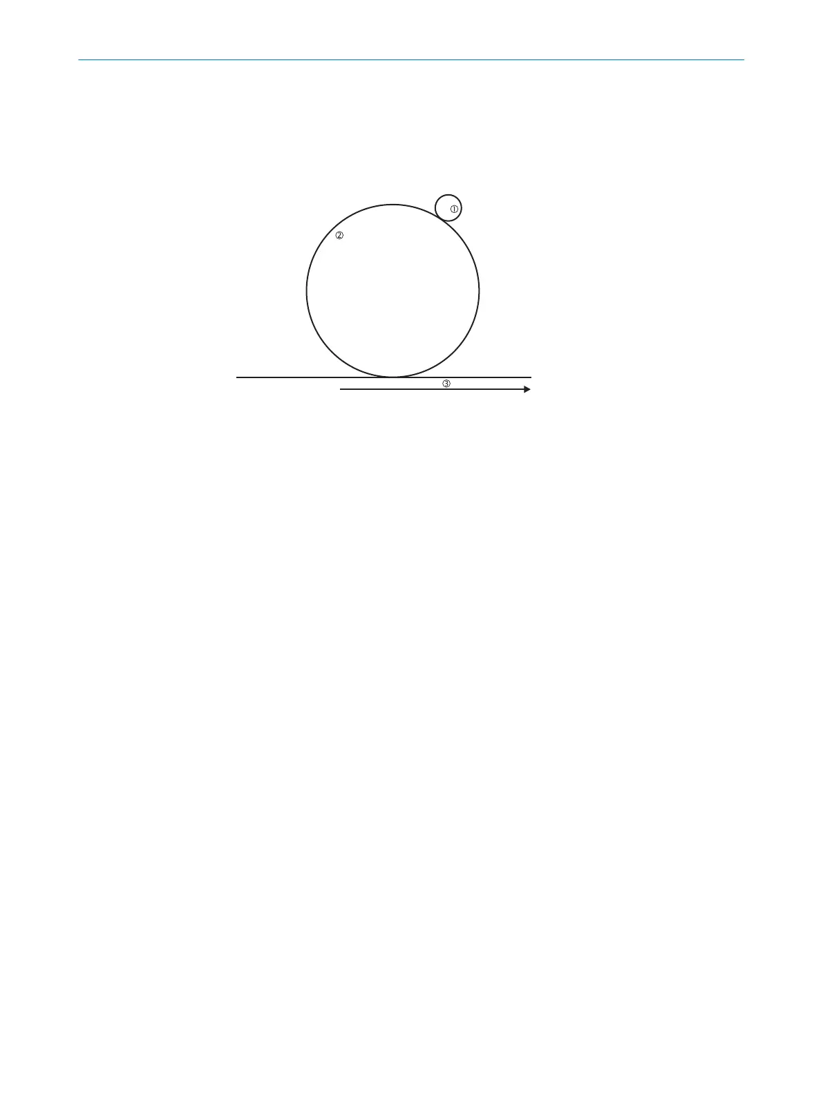
Figure 58: Calculation of pulses per cm travel
1
Friction wheel ø 3.5 cm
2
Forklift truck ø 35 cm
3
Distance covered by the AGV
Calculating the number of pulses per centimeter
Ex
ample:
•
The wheel on a forklift truck has a diameter of 35 cm.
•
The friction wheel on which the incremental encoder is mounted has a diameter of
3.5 cm.
•
The incremental encoder used supplies 1,000 pulses per revolution.
Circumference of the forklift truck wheel = d × π = 35 cm × π = 109.96 cm
One revolution of the forklift truck wheel corresponds to ten revolutions of the friction
wheel and therefore 10,000 pulses from the incremental encoder.
The number of pulses of the incremental encoder per centimeter of distance covered
by the vehicle is therefore:
pulses/cm = 10,000 : 109.96 = 90.94
When configuring the incremental encoder in the CDS, you therefore need to enter the
rounded value “91” in the Pulses per centimeter field. The user software uses this value to
calculate the maximum permissible speed of the vehicle.
7.7.2 Tolerances allowed on the dynamic inputs
As a rule, the same pulse frequency is present at the dynamic inputs when a vehicle
mo
ves in a straight line. On driving around bends or in case of wear e.g., of the vehicle’s
tires, the values at the two inputs may, however, vary.
The speed values from the two incremental encoders may only differ from each other
by a tolerance that can be configured. Deviations are allowed only for a certain time
window depending on the speed, see figure 59, page 81.
The maximum percentage deviation between the two encoder speeds that can be con‐
figured is 45%. During this process the higher of the two speeds (irrespective of
whether with positive or negative sign) is used as the reference for this calculation as
well as the vehicle speed.
7 C
ONFIGURATION
80
O P E R A T I N G I N S T R U C T I O N S | S300 8010948/ZA21/2020-06-18 | SICK
Subject to change without notice

 Loading...


