Complementary information
•
In t
he phases before and after switching, only the minimum distances calculated
for the individual monitoring cases apply.
•
The preceding considerations are provided exclusively for the purposes of select‐
ing the optimum switching time.
•
If the timing for the switching cannot be exactly defined, e.g., due to the variable
processing speed of the machine, or if advancing of the timing results in prema‐
ture termination of the monitoring of the initial area, the two protective fields must
partially overlap.
Further topics
•
"Input delay", page 83
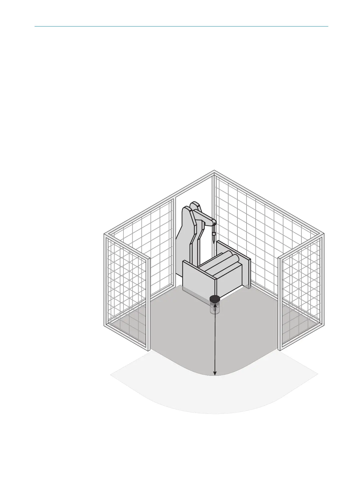
4.3.4 Stationary applications in horizontal operation
This type of protective device is suitable for machines and systems where, for example,
a ha
zardous area is not completely surround by a physical guard.
Figure 28: Horizontally mounted stationary application
F
or a horizontal stationary application, you determine the following:
•
The protective field size to maintain the necessary minimum distance
•
The height of the scan plane
PROJECT PLANNING 4
8010948/ZA21/2020-06-18 | SICK O P E R A T I N G I N S T R U C T I O N S | S300
37
Subject to change without notice

 Loading...


