b
D
epending on the application, use suitable cable glands on the bottom or rear.
b
Use EMC-compliant cable glands for the EFI cables.
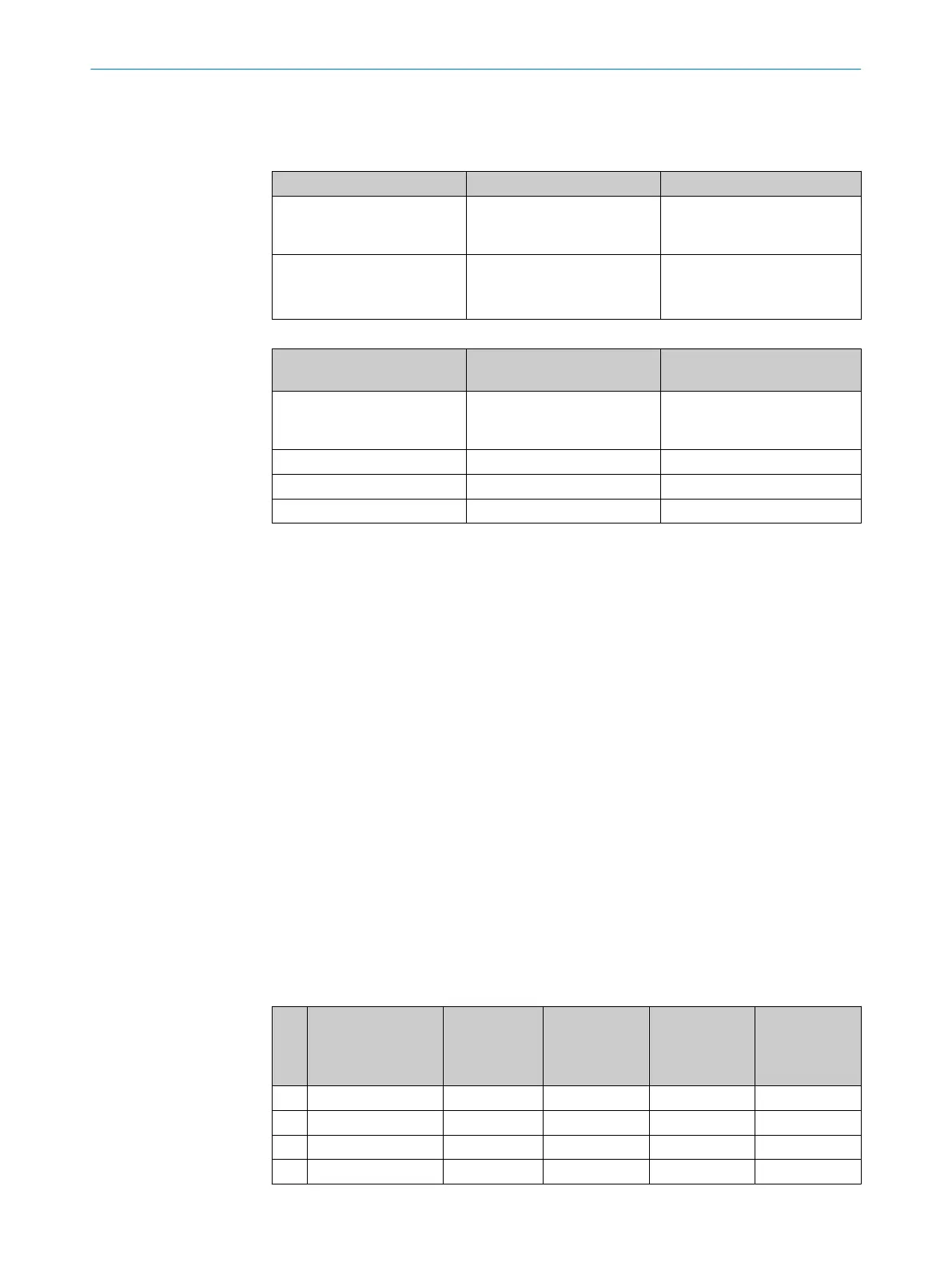
Table 8: Use of the supplied cable glands
Cable gland Cable diameter Use
M16 5 mm … 9 mm
•
System cables (supply volt‐
age, outputs, static inputs,
universal I/Os)
M12, EMC-compliant 3 mm … 6.5 mm
•
E
FI
•
Incremental encoder
•
RS422 data cables
Table 9: Recommended wire cross-sections
Cable
Recommended wire cross-
sec
tions
Shielded
System cables (supply voltage,
outputs, static inputs, univer‐
sal I/Os)
0.5 mm² … 1 mm², 9 … 15
wires
No
1)
EFI 2 × 0.22 mm² Yes
Incremental encoder 4 × 0.25 mm² Yes
RS-422 data cables 4 × 0.25 mm² Yes
1)
A shield is recommended if there are high EMC charges in the surroundings.
Further topics
•
"Pr
e-assembled system plug", page 71
•
"System plug", page 137
•
"Connecting cables for self-assembly", page 138
6.4 Pre-assembled system plug
SX0B-B1105G, SX0B-B1110G, SX0B-B1114G, SX0B-B1120G
•
F
or S300 Standard
•
With 11 wires, unshielded (M16 cable gland)
•
5, 10, 14 or 20 m long
SX0B-B1105J, SX0B-B1110J
•
For S300 Professional and Expert with dynamic inputs
•
With 11 wires, unshielded (M16 cable gland)
•
With 2 M12 cable glands (for incremental encoders), enclosed loosely
•
5 or 10 m long
SX0B-B1505G, SX0B-B1510G
•
For S300 Advanced, Professional and Expert with static inputs
•
With 15 wires, unshielded (M16 cable gland)
•
5 or 10 m long
Table 10: Pin assignment on pre-assembled system plugs
Pin Signal Wire color SX0B-B1105G
SX0B-B1110G
SX0B-B1114G
SX0B-B1120G
SX0B-B1105J
SX0B-B1110J
SX0B-B1505G
SX0B-B1510G
FE Functional earth Green
C C C
1 24 V DC Brown
C C C
2 0 V DC Blue
C C C
3 OSSD1 Gray
C C C
ELECTRICAL INSTALLATION 6
8010948/ZA21/2020-06-18 | SICK O P E R A T I N G I N S T R U C T I O N S | S300
71
Subject to change without notice

 Loading...


